This thread has been locked.

If you have a related question, please click the "Ask a related question" button in the top right corner. The newly created question will be automatically linked to this question.

DS90UB964-Q1: Interface forum

Part Number: DS90UB964-Q1

Hi  

   I'm very glad to get your reply,But There are some questions I don't understand,as follows
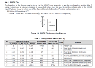
1:Noticing  the picture on the rightI want to know the difference between 0 and 1 in the COAX field in the table?

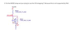
      How do I configure the mode pin?


2:Currently, the I2C address of the serial device and sensor cannot be scanned. Is it related to the Mode pin configuration? Have you encountered similar problems and how to solve them?

  • Hello,

    Please see the explanations to your questions below:

    1. The 0 and 1 in the COAX field indicate which configuration is being used. A 0 indicates STP and 1 indicates coax mode. So mode 1 is a STP configuration using RAW12 LF mode. You should configure the mode pin so that the resistors placed in the R3 and R4 position match those suggested in the table to create a voltage choosing the desired mode. Using mode 1 as an example again, R3 = 118 kohm and R4 = 30.9 kohm, which creates a voltage of 0.367 V.

    2. No, the mode pin does not impact the I2C address. The I2C address of the device is controlled by the IDX pin, which is configured the same way as the mode pin. Please see section 8.5.1 of the datasheet for more details. In order to communicate with other devices like a sensor using I2C, the I2C address and alias must be stored in the DS90UB964s registers and passthrough needs to be enabled. Pass through can be enabled in register 0x58, the I2C ID in register 0x5D, and the I2C alias in register 0x65.

    Regards,

    Darrah

  • Hi 

        I‘m very glad to receive your reply,

        At present, we have encountered a problem that we cannot scan the I2C address of the serializer, and the deserializer adopts the coaxial line mode. Please refer to the diagram for the differences in the Demo board. Will the differences lead to this problem?

  • It looks like you do have a power over coax configuration so coax mode being displayed is correct. Do you have lock between the des and ser? The I2C address of the serializer should be autoloaded in the registers once lock is stable. There are various ways to build a POC network, but if the network does not meet the required specs, there could be issues with the device being properly powered and behaving as expected. Has any simulation or testing been done on the return loss or insertion loss? It is recommended to use one of the provided networks as they have already been validated.