This thread has been locked.

If you have a related question, please click the "Ask a related question" button in the top right corner. The newly created question will be automatically linked to this question.

Connect SN75LVDS83A to Omapl138 LCDC interface 16bpp mode

Other Parts Discussed in Thread: OMAPL138, SN75LVDS83A

hi,

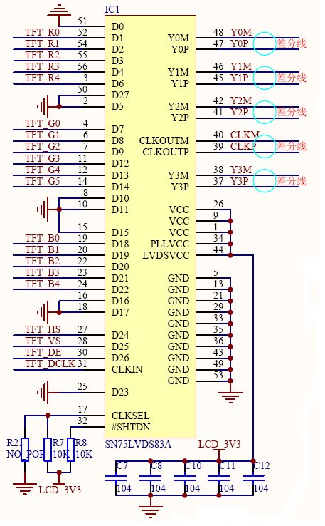
      I want to use SN75LVDS83A for LCD interface,    When I use 16bpp mode, I want to know how connect SN75LVDS83A D0~D23 to omapl138 LCDC interface, Specially  TFT565  RGB connect mode.

Thanks/

  • Hello Ben,

    The unused data inputs (D#) should connected to ground. Please see Figures 14 to 17 of the SERDES datasheet(http://focus.ti.com/lit/ds/symlink/sn75lvds83a.pdf)

    When you say "16bpp" do you mean 16 bits per pixel? How many bits for each color?

    Regards.


  • ElIAS,


         Thanks for your replay.    Yes,  "16bpp" means 16bits per pixel. RGB565 mode,  red color 5bits, green color 6bits ,blue bits 5bits .

    when I check the sn75lvds83a.pdf , it shows 12bpp, 18bpp,24bpp  mode.  Below is my connection mode. Am i right? thanks! 

    TFTR0~TFTR4 singals come from LCDC red color singals;

    TFTG0~TFTG5 singals come from LCDC green color singals;

    TFTB0~TFTB4 singals come from LCDC blue color singals;

  • Hi Ben, are you connecting to a 16-bit panel, and do you have the panel datasheet?  The panel should have an expected bit order sequence, and that is what will determine how to connect the parallel colors to the LVDS83A.

    For example, see this panel datasheet on Page 17.  It shows the LVDS bit order for 18-bit and 24-bit modes.

    Once you determine the needed bit order for the panel, it may work to run the OMAP in 18-bit mode to drive the 16-bit panel, by not using the LSB's for green and blue, which will cause greater steps between each shade.

    Thanks,
    RE

  • hi RE,

           Thanks.yes I have the panel datasheet, pannel type is G104VN01 V1, it is same as G104SN01 V1.  The problem is the Omapl138 LCDC interface have 16bits data path D0~D15,  when the pannel work at 18bit mode or 24bit mode,  some input singals of the pannel must be connected to ground or Vcc.  which bit is not use determined by the pannel, right?   So what paraterms or timing graph of the pannel I apply  with to solve the problem.

    Thanks!8407.AUO_G104VN01_V1_V0.0_02.11.2009.pdf

  • Ok Ben, I understand your situation now, and I have the answer.

    The LVDS83A datasheet's Figure 16 shows a suggestion for connecting a 12-bit GPU to 18-bit LCD.  I understand your situation involves a 16-bit GPU and 18-bit LCD.  It's an easier situation.  The LCD has 2 extra bits, 1 for red and 1 for blue.

    Like the datasheet's example, you have a choice for how to connect the extra LSB on red and blue.  You can connect it to GND, for linear steps but not quite a full dynamic range (111110 would be the max red).  Or you can connect it to your MSB, R4, for a full dynamic range but a non-linear step.  I created the attachment, which compares these two options.

    Your panel's expected bit order matches Format 1.  The picture of your connections looks good, for choosing to connect the extra 2 bits to GND.

    Thanks,
    RE

    5265.16b GPU to 18b LCD.xls

  • hi Re,

         Thanks so much! your analysis is so professional.  How about 16bit GPU to 24bit LCD. is the same as 16bit GPU to 18bit LCD?

    Is the step the smaller the better,right?

    Thanks!

  • Yes, smaller steps are better.  If you view a gradient and steps are big, you'll see banding.

    I think 16-bit to 24-bit is the same situation as 12-bit to 18-bit, where you're lacking 2 bits per color.  Two choices for how to handle that are shown at the top of my Excel sheet.  But I think you'd get better results running the panel in 18-bit mode for your 16-bit GPU.

    Thanks,
    RE

  • ok,thanks very much, I got it!

  • hi RE,

         Here is a sheet that I connet a 16bits GPU to 24bits pannel,  Differences are  obviously betweent non-linear step and linear from the graph.

    which one you recommended?4265.16bits to 24bits pannel.xls

  • In your case, I recommend using 16-bit to 18-bit (running the LCD in 18-bit mode).

    But if you insist on using the LCD in 24-bit mode, attached shows 2 more possible implementations.

    Thanks,
    RE

    5344.16b GPU to 18b LCD.xls