This thread has been locked.

If you have a related question, please click the "Ask a related question" button in the top right corner. The newly created question will be automatically linked to this question.

TFP401A: HDMI source does not transmit data when connected to HDMI to LVDS bridge

Part Number: TFP401A

Hello and thank you for taking time to help me with my confusion i really appreciate it.

I am designing a HDMI to LVDS bridge using a HDMI to DVI (TFP401APZP) and then a DVI to LVDS (SN65LVDS93AIDGGRQ1). The schematic using both can be seen in the attached PDF.6332.Schematics.pdf

The settable pins on the SN65LVDS93AIDGGRQ1 are as follows:

Output Power Down = 3.3V

Staggered Pixel Select = 3.3V

Pixel CLK Setting = GND

Output Drive Strength = GND

Power Down = 3.3V

ODCK Format = GND

ODCK Polarity = 3.3V

I am having difficulties with getting the HDMI source (My computer) to begin transferring visual data to the PCB (all of the differential pairs are completely still). I have tied together the Hot-Plug detect to the 5V provided by the HDMI source to indicate that there is a device present with no effect. (There should be a 1k resistor between the pins however i didnt have room to solver since the pins are so close together - though i dont believe this should be an issue)

After then doing some more reading I came to the conclusion that its the DDC/EDID requirement not being fulfilled. This is where i meet my problem of, how do I encode and communicate the TFT data so that when the HDMI is plugged in the resolution and other necessary parameters are transmitted? Am i correct it this deduction?

Do I need to use some I2C Eeprom connected to pin 15 & 16 on the HDMI connector with the PC providing the I2C clock to begin communication?

The DVI output from the first chip is then connected to SN65LVDS93AIDGGRQ1 that outputs an LVDS signal to the TFT.

The TFT i am using is attached below: its a 10" 1024 x 768

g104xce-l01_datasheet.pdf

I will continue to do some reading, I'm at the point where i dont know what else could be causing the issue.

Thank you once again for your help, i really look forward to learning what I'm missing.

Best Regards,

Kacper

  • Kacper

    You can connect an I2C EEPROM to pin 15 (DDC_CLK) and pin 16 (DDC_DATA) and have it pulled up to 5V. You also need to make sure you program the EEPROM with a valid EEID information. 

    You can also order an EDID controller and use it to generate the necessary EDID information, https://www.allion.com/test-fixture/ajsc-1/.

    When you probe the HDMI output from the PC, did you probe it with TFP401A turned on?

    Thanks

    David

  • Hi David,

    Thank you for your response.

    I have looked into using I2C EEprom and connect it to a microcontrolled in parallel with the HDMI. The idea is that i could program the EEID information using the microcontroller so that it can then be read by the HDMI when connected.

    I would then program the EDID structure onto into the memory. https://en.wikipedia.org/wiki/Extended_Display_Identification_Data

    I however still have some things i dont understand:

     - The EDID. How do i know what information to place into the EEprom? Is the manufacturer data necessary? can i leave it all blank, only focusing on the display parameters?

     - At what address do i store the EDID data in the Eeprom, in order for the hdmi to know where to start. Additionally, does the hdmi know how many bytes to read from the strating address to read all the necessary data?

    If you wouldnt mind being clearer as to how to connect the EEprom and how to address it/store the data i would really appreciate it.

    Thank you

    Kacper

  • Kacper

    I attached an EDID as example.

    <?xml version="1.0" encoding="utf-8"?><DATAOBJ><HEADER TYPE="DID" VERSION="1.0" /><DATA><BLOCK0>00FFFFFFFFFFFF005E8C0100010000001A140103808048780ADAFFA3584AA22917494B2108003140454061408180010101010101010108E80030F2705A80B0588A00BA992100001E023A801871382D40582C4500BA882100001E000000FC0048444D492D5450410A20202020000000FD0014FF0FFFFF000A202020202020016B</BLOCK0><BLOCK1>02037DF050C2C3C47675C5C6C7C8C9CACBCCCDCECF5ED0D1D2D3D4D5D6D7D8D9DADB616066656B6A100504035D025F6264685E145C5C5B5A595857564E4D4C4B4A49484746403F1112136763051F202122230907016E030C001000F83C2F8880010203046DD85DC4017888673F4A2CCF673FE60FFFFFFFFF03E305FF010000AC</BLOCK1></DATA></DATAOBJ>

    For detailed information on EDID, I would refer you to the EDID spec, https://glenwing.github.io/docs/VESA-EEDID-A2.pdf. You have to make sure the display parameter provided in EDID matches with the panel you are using.

    Thanks

    David

  • Hi David,

    I really apprecaite your help. However i have some more questions before i can fully understand and apply the EDID to my design.

    https://glenwing.github.io/docs/VESA-EEDID-A2.pdf

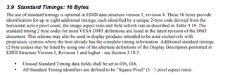
    On the EDID standard file you provided (thank you for this), I dont understand why multiple timing standards are necessary for my TFT to work properly. This is the data stored from adress 26h to 35h. I have provided data for standard timing 1 and i am confused about the rest of the timing standards. Am i able to leave these as 0x0100 or do i need to provide another value, and if so what value should it be?

    Additionally i have provided some of the first of the 18 byte descriptors (address 36h to 7Dh), i am waiting the manufacturer of the TFT to provide the rest of the information since its not in the datasheet. However when the first 18-Byte Data Block 'Preffered timing Mode' is filled in, what should be put into the remaining 3 18-Byte blocks? Is the solution to leave these empty and put the value 0x00 at address 7Eh to symbolise there is only one block of timing data?

    Thank you for your help with this, its most certainly getting me much closer to the solution, i really appreciate it.

    Best Regards,

    Kacper

  • Hi David,

    As requested by Kacper, I am uploading this file below for clarity:

    EDID 1024x768.zip

    Thank you and best regards,

    Gerald

  • Kacper, Gerald

    These questions are outside of TFP401A so I would refer to the EDID spec, in particular section 3.9 

    Thanks

    David