This thread has been locked.
If you have a related question, please click the "Ask a related question" button in the top right corner. The newly created question will be automatically linked to this question.
Hello,
I am designing a test board that requires a variety of throughput signals, but the one I'm struggling with is the MIPI CSI. I have four cameras that need to be tested, but only enough hardware to have one input. My current idea is to use a multiplexer, and it seems only 2:1 multiplexers exist for 10+ channels. Because I need to test four different 4 channel CSI signals, my thought is to use three 2:1 multiplexers in a cascade configuration. If this is unfeasible or there is a better way, I am all ears.
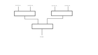
This is my rudimentary block diagram of how I think it could work.
Thank you in advance.
Hi,
Please see this e2e link, https://e2e.ti.com/support/interface-group/interface/f/interface-forum/1115970/ts3dv520-ts3dv520. You can use TS3DV642 to accomplish this. Each TS3DV642 adds certain amount of insertion loss. Depends on the data rate, I would add a retimer such as DPHY440 at the TS3DV642 output to provide signal compensation.
Thanks
David
If I understand correctly, it would be beneficial to add a retimer to the output of the last multiplexer in the cascade? Are there other things I need to add to this kind of circuit to ensure stability? I plan to add ESD diodes, but otherwise just pass through to these ICs.
Hi,
It would be beneficial to add a retimer to the output of the last multiplexer in the cascade -> This is correct.
Each MUX would add certain amount of insertion loss, so depending on the data rate, we want to make sure the total insertion loss (trace, via, connector, MUX, etc) before the retimer is kept within the retimer EQ compensation capability. For DPHY440, its max EQ compensation is 5dB at 1.5Gbps.
Thanks
David