This thread has been locked.

If you have a related question, please click the "Ask a related question" button in the top right corner. The newly created question will be automatically linked to this question.

SN65LV1224B: unlock issue depending on the boards

Part Number: SN65LV1224B
Other Parts Discussed in Thread: SN65LV1023A

Hello,

My customer has unlock issue on SN65LV1224B after replacing from DS92LV1212A(They didn't have any unlock issues at all when they had used DS92LV1212A).  My customer's system is similar to the following thread except they use MT9V034 and 26.66MHz clock.

https://e2e.ti.com/support/interface-group/interface/f/interface-forum/769259/sn65lv1224b-sync-lock/2889362?tisearch=e2e-sitesearch&keymatch=SN65LV1224B#2889362

They have unlock issue depending on the boards.  If they probe the LVDS lines, they don't see unlock issue, but if they leave the lines unprobed, they do unlock issue.  Would you please tell me how they should do for fixing the unlock issue?  Can they add some capacitors on the lines?  If so, how big capacitors they can add?  Note that they confirmed the REFCLK is within +/-100ppm.  Note also that they removed the PU/PD resistors at the LVDS lines.

1.Power on the system -> /LOCK=Lo -> Normal operation

2.System in standby mode -> /LOCK=Lo -> Normal operation

3.System goes to operational mode -> /LOCK=Hi -> Abnormal operation

4.Probing the LVDS lines -> /LOCK=Lo -> Normal operation

5.Leaving the LVDS lines unprobed -> /LOCK=Hi -> Abnormal operation 

Best Regards,

Yoshikazu Kawasaki

  • Hello Yoshikazu,

    What type of scope probe is the customer using (Active/Passive and High-Z) and how are they measuring? And is there a 100 Ω termination resistor close to the ±Y inputs?

    Regards,

    Josh

  • Hello Josh-san,

    Thank you for your comments.  I'm checking the items you asked.  Please wait for a moment.

    Best Regards,

    Yoshikazu Kawasaki
  • Hello Kawasaki-san,

    Thanks for following up. The reason why I'm asking is the customer could be experiencing loading effects from the scope probe. This can result in a circuit performing differently if the input resistance is low and capacitance is high.

    When measuring the differential inputs we recommend using a high impedance, low capacitance (<1pF) probe.

    Regards,

    Josh

  • Hello Josh-san,

    Thank you very much for your comments again.

    They used passive probe this time, but will do active probe next and provide the results later.

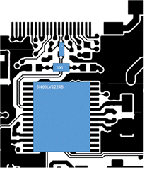
    The termination resistor looks to be placed far from the input pins as shown below.  Would you please give me your comments again about the probe and termination resistor?  What do you think the root cause would be for the unlock issue?  Would it be impedance matching?  How would they have to do to fix the issue?

    Best Regards.

    Yoshikazu Kawasaki

  • Hello Kawasaki-san,

    Yes, when probing a signal with a passive probe, the low impedance of the probe will be added on to the circuit of your signal. Instead of having the trace impedance and termination resistor, you will also have the probes resistance. That's why we recommended using probes with a high impedance, low capacitance. This way the probe and its internal circuit isn't a factor in your measurement.

    For the termination resistor, we need to make sure this is located closest to the input of the 1224B and the characteristic impedance (Zo) is 50 Ω. See picture below for reference.

    It seems like impedance matching could be the issue here. That's why performing the test again with high impedance probes is necessary.

    Regards,

    Josh 

  • Hello Josh-san,

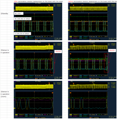
    They took scope shots with FET probe this time as shown below, but the results are the same.

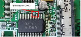
    They replaced the termination resistor to the closest point as shown below, but the unlock issue sill exists.

    Questions

    1. Would you please tell me the conditions for SN65LV1224B to unlock?

    2. Do you have any other ideas to fix the unlock issue?

    3. What do they have to do more to replace DS92LV1212A by SN65LV1224B?

    4. The DS92LV1212A datasheet on page 11 says the recovering from LOCK loss as shown below, but is this the same for SN65LV1224B?

    Recovering from LOCK Loss
    In the case where the Deserializer loses lock during data
    transmission, up to 3 cycles of data that were previously
    received can be invalid. This is due to the delay in the lock
    detection circuit. The lock detect circuit requires that invalid
    clock information be received 4 times in a row to indicate
    loss of lock. Since clock information has been lost, it is
    possible that data was also lost during these cycles. Therefore,
    after the Deserializer relocks to the incoming data
    stream and the Deserializer LOCK pin goes low, at least
    three previous data cycles should be suspect for bit errors.
    The Deserializer can relock to the incoming data stream by
    making the Serializer resend SYNC patterns, as described
    above, or by random locking, which can take more time,
    depending on the data patterns being received.

    Best Regards,

    Yoshikazu Kawasaki
  • Hello Kawasaki-san,

    Thank you for providing an update and the scope waveforms. Due to the U.S holiday on Feb 20th (Monday), there will be a delay in my response. Please give us a couple of days to look at the data and come up with a suggestion. 

    Regards,

    Josh 

  • Hello Josh-san,

    I'm asking to confirm the external parts for the sensor(MT9V034) since the noise on LVDS signals improved by replacing the termination resistor, but it still has enough noise to show unlock, so I supposed the capacitors on LVDS power might not be enough.  Would you please give me your comments for my questions in my previous post and suggestions which could fix the unlock issue?

    Best Regards,

    Yoshikazu Kawasaki
  • Hello Josh-san,

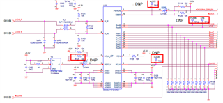
    I got another plot showing the power supplies how those are stable at around unlock issue happened since the datasheet says "The deserializer stays in lock until it cannot detect the same data boundary (stop/start bits) for four consecutive cycles. Then the deserializer goes out of lock and hunts for the new data boundary (stop/start bits)".  The supplies look stable for four consecutive cycles before the unlock happens.  Will this plot give you a hint to cause the unlock?  It is a little bit noisy when the unlock issue happened, so should I ask them to add a capacitor at VDDLVDS on the sensor despite the fact that it worked well with DS92LV1212A?

    Best Regards,

    Yoshikazu Kawasaki

  • Hello Kawasaki-san,

    What is the data going into the inputs, D0-D9?

    To achieve Lock: The input/start-up pattern needs to avoid having a 01 transition to start with because the SN65LB1224B is looking for 10 to lock. The datasheet refers to sending a pattern of six 1's and six 0's to allow the deserializer to lock. This should be the following pattern: 101010101010. You can refer to Figure 17 of the datasheet for an example of the SYNC pattern.

    How is the customer routing AVCC? Could you share the power routing and capacitors used? 

    Here is a complete guide in migrating from the DS92LV1212A to SN65LVDS1224B (SLLA435)

    Regards,

    Josh

  • Hello Josh-san,

    Thank you for your comments.  Please let me confirm the following items.

    > What is the data going into the inputs, D0-D9?

    #1 : If I understand correctly, the synch pattern is required if the serializer is used as shown in the datasheet like this for rapid synchronization.

    Rapid Synchronization: The serializer has the capability to send specific SYNC patterns consisting of six ones and six zeros switching at the input clock rate.

    In this case. their system doesn't have serializer, so it should be for random lock synchronization.  Therefore I understand the input pattern can be random.  Am I wrong?  The issue depends on the boards without serializer, but the synch pattern is required as you mentioned?

    Random-Lock Synchronization: The deserializer can attain lock to a data stream without requiring the serializer to send special SYNC patterns.

    Could you share the power routing and capacitors used?

    #2 : Which format would you prefer?  They don't use Altium, so pdf files for each layer is OK for you?

    Here is a complete guide in migrating from the DS92LV1212A to SN65LVDS1224B (SLLA435)

    #3 : They looked at the apps note and confirmed the REFCLK is +/-100ppm and removed the PU/PD.  Would you please tell me exactly what else they need to do?

    Best Regards,

    Yoshikazu Kawasaki

  • Hello Kawasaki-san,

    #1: This is correct. The Rapid Synchronization refers to the serializer (in this case the SN65LV1023A) sending a specific pattern. Since the customer's system doesn't use a serializer IC, the MT9V034 needs to provide 12 Bits (1 Start bit, 10 Data bits, 1 Stop bit). Without a Start/Stop bit, the deserializer cannot go into lock.

    #2: PDF will work fine

    #3: The REFCLK tolerance is the main difference between the 1212A and 1224B. Looking at another thread with a similar system as the customers, is it possible to try a smaller tolerance value like 10ppm? This is the thread I'm referring to: SN65LV1224B: Sync Lock

    Regards,

    Josh

  • Hello Josh-san,

    Thank you very much for supporting me on this thread.  I haven't got any replies from my customer even though we asked the current status a few times.  I believe they've fixed the issue by themselves after providing the information to find the root cause.  Please let me close this thread and open another one if I get questions from my customer.

    Best Regards,

    Yoshikazu Kawasaki