This thread has been locked.

If you have a related question, please click the "Ask a related question" button in the top right corner. The newly created question will be automatically linked to this question.

DP83867CS: 10Base-Te Compliance Test failed

Part Number: DP83867CS
Other Parts Discussed in Thread: DP83867E

Hi Team,

When my customer did compliance test of their DP83867CSRGZR board under 10Base-Te, the compliance test results became as follows,
I would appreciate any advice on their compliance test results.
In addition, the results are the same as the e2e test results below.

1.e2e URL
e2e.ti.com/.../dp83867ir-10base-te-100base-tx-1000base-t-compliance-test

2.10Base-Te Test results
- 2 fails at the following items,
1) TP_IDL Template, with TPM (last bit CD0) : Fail at Load2
2) TP_IDL Template, with TPM (last bit CD1) : Fail at Load2

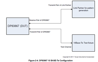
3.10Base-Te Test condition
(1)Test fixture (10Base-Te with TPM):640-0581-001 (EEE-TPA-ERK)
 ・The above is a test board dedicated to 10Base-Te.
(2)Test PatTern
・at 10BT TEST,Since the link partner cannot output pseudo random,
 the pseudo random signal by the PHY BIST (0x16) function was used as the test signal.
◆Below, register settings
 0x1f 0x8000, PHY RESET
 0x00 0x0100, 10Base-T / Te mode
 0x10 0x5008, Forced MDI mode
 0x16 0xd804,
(3)oscilloscope:KEYSIGHT


I found a thread related to this issue on the E2E community, but I'm not sure if it was resolved.
Please tell me the following points.


<Question1>
As per the forum answer below, I tried to write the GPHY register.
-------------------------------------------------------------------------------------------
2. For 10BTe :
a. Measure TP_IDL on load 2 (where it was failing earlier) with following extra configuration :
reg<0x009F> = 0xCCCC.
--
Regards,
Vikram
-------------------------------------------------------------------------------------------
By implementing the above settings, the amplitude increased by 0.2V.
Also, the TP_IDL template (LOAD2) now passes.
But it failed with 10BASE-Te peak differential voltage.
・Measured value: 2.129V
・Pass limit: 1.540V <= VALUE <= 1.960


Is it possible to finely adjust the differential amplitude of 10BASE-Te?
Is there any other way to increase the output level?


<Question2>
It was reported that the e2e community and the DP83867 EVM had similar results.
Please let me know the compliance test results of the DP83867 EVM so that I can compare the results.


<Question3>
Has the E2E community issue below been resolved?

e2e.ti.com/.../dp83867ir-10base-te-100base-tx-1000base-t-compliance-test

  • Hi,

    Can you please share the compliance test report where you are noticing failures? Are the schematics of customer board reviewed by our team, if not can you please request customer to fill out the attached schematic checklist and share their schematics for review ?

    DP83867_Schematic_Design_Review_Checklist.xlsx

    Regards,
    Rahul

  • HI,

    I share the compliance test report below.
    This is the result of testing with the DP83867E SGMII EVM.


    1.Test results
    (1)reg<0x009F> Default value: 10BASE-Te TP_IDL(LOAD2) compliance test results.
    reg<0x009F> = 0xBBBB. 【Results:FAIL】

    10BASE-Te_TP_IDL_TI_board_0x9F_0xBBBB_FAIL.pdf


    (2)This is the result of testing 10BASE-Te TP_IDL(LOAD2) by increasing the differential amplitude of PAIRA and writing the following register value.
    reg<0x009F> = 0xBBBC. 【Results:PASS】

    10BASE-Te_TP_IDL_TI_board_0x9F_0xBBBC_WRITE_PASS.pdf


    (3)This is the result of performing a 10BASE-Te peak differential voltage test by implementing a countermeasure for 10BASE-Te TP_IDL(LOAD2), increasing the PAIRA differential amplitude, and writing the following register values.
    reg<0x009F> = 0xBBBC.【Results:FAIL】

    10BASE-Te_PEAK_DIFF_WITHOUT_TI_board_0x9F_0xBBBC_WRITE_FAIL.pdf


    2.Schematic and board design
     Below is the schematic and board design information for the DP83867E SGMII EVM I purchased.

    snlu209_Schematic and board design.pdf


    Can you tell me why the DP83867E SGMII EVM cannot PASS?
    Please answer Question 1 to 3.

  • Please let me review these results and get back to you.

    Did you try the reg<0x009F> = 0xCCCC value and it fails both the TP_IDL and Peak differential ?

    Regards,
    Rahul

  • HI,

    I will answer below.

    >Did you try the reg<0x009F> = 0xCCCC value and it fails both the TP_IDL and Peak differential ?
    TP_IDL succeeds, Peak differential fails.
    I share the compliance test report below.


    1.This is the result of testing 10BASE-Te TP_IDL(LOAD2) by increasing the differential amplitude and writing the next register value.
    reg<0x009F> = 0xCCCC.【Results:PASS】

    10BASE-Te_TP_IDL_TI_board_0x9F_0xCCCC_WRITE_PASS.pdf


    2.This is the result of testing 10BASE-Te peak differential voltage by increasing the differential amplitude and writing the next register value.
    reg<0x009F> = 0xCCCC.【Results:FAIL】

    10BASE-Te_PEAK_DIFF_WITHOUT_TI_board_0x9F_0xCCCC_WRITE_FAIL.pdf

  • Thank you for sharing the reports, let me review them and update you my feedback.
    Please give me time till mid next week, as I am currently swamped with multiple E2E threads.

    Regards,
    Rahul

  • Hi, Rahul
    Thank you for your confirmation.
    What is the status of the above confirmation?

  • Hi,

    Apologies for the delay. Will have an update in some time.

    Regards,
    Rahul

  • Hi,

    ◆Below, register settings
     0x1f 0x8000, PHY RESET
     0x00 0x0100, 10Base-T / Te mode
     0x10 0x5008, Forced MDI mode
     0x16 0xd804,

    In the register configuration shared above, reg 0x16 you are configuring the PHY in digital loopback.
    Reg 0x16, Bits [5:2] = 0001

    Digital Loopback includes the entire digital transmit to receive path. Data is looped back prior to the analog circuitry.

    Can you configure the PHY in reverse loopback and perform the tests ?
    Also, please share the register settings being used.

    Guide to compliance tests on DP83867:
    https://www.ti.com/lit/ml/snla239b/snla239b.pdf?ts=1680300164201&ref_url=https%253A%252F%252Fwww.google.com%252F

    Thanks,
    Rahul

  • HI,Rahul

    I set it to reserve loopback (0x16 0X0020) above and share the results I see.
    I followed How to Configure DP838xx for Ethernet Compliance Testing (SNLA239B), connected a packet generator as a link partner (random packet generation), and connected and verified the test fixture as shown below.
    I connected and confirmed the test fixture as follows.

    The DP83867E SGMII EVM was tested and the result was FAIL.
    I will share the register settings and the compliance test report.
    I share the register settings below.

    ◆Below, register settings
    10 Base Standard:
    Reg 0x001F = 0x8000 //reset PHY
    Reg 0x0000 = 0x0100 //programs DUT to 10Base-T/Te Mode
    Reg 0x0010 = 0x5008 //programs DUT to Forced MDI Mode
    Reg 0x0016 = 0x0020 //programs DUT to Phy Loop-Back(reserve loop back)

    I share the compliance test report below.

    10BASE-Te_TP_IDL_LOAD2_TI_board_LOOPBACK_FAIL.pdf

    Why can't the DP83867E SGMII EVM pass?
    Please share your DP83867E SGMII EVM compliance results.
    Also, please answer questions 1 through 3.
    I urgently need to determine if this device can be used.
    By when can I get an answer to the above question?

  • Let me review your comments and update my feedback.

    Regards,

    Rahul

  • Thank you for sharing the details and testing it with the correct setup.

    We do not have a 10BASE-Te compliance report with DP83867 SGMII EVM.

    Looking at the test report shared EVM is failing TP_IDL with TPM ? Is this the only failure noticed ?

    Thanks,
    Rahul

  • HI,Rahul

    Thank you for answering.
    I will answer below.

    >Looking at the test report shared EVM is failing TP_IDL with TPM ?
    >Is this the only failure noticed ?
    I did a 10BASE-Te compliance test on the DP83867 SGMII EVM and it failed only with TP_IDL_Template with TPM(LCD0/1)(LOAD2).
    Others are PASS.

    1.10BASE-Te test items and results
    TP_IDL_Template with TPM(LCD0)(LOAD1):PASS
    TP_IDL_Template with TPM(LCD0)(LOAD2):FAIL
    TP_IDL_Template with TPM(LCD0)(LOAD3):PASS
    TP_IDL_Template with TPM(LCD1)(LOAD1):PASS
    TP_IDL_Template with TPM(LCD1)(LOAD2):FAIL
    TP_IDL_Template with TPM(LCD1)(LOAD3):PASS

    TP_IDL_Template without TPM(LCD0)(LOAD1):PASS
    TP_IDL_Template without TPM(LCD0)(LOAD2):PASS
    TP_IDL_Template without TPM(LCD0)(LOAD3):PASS
    TP_IDL_Template without TPM(LCD1)(LOAD1):PASS
    TP_IDL_Template without TPM(LCD1)(LOAD2):PASS
    TP_IDL_Template without TPM(LCD1)(LOAD3):PASS


    Please confirm the following contents.

    【Question 1】
    I would like to see if there is a way to improve with TP_IDL_Template with TPM(LCD0/1)(LOAD2).
    We believe that improvements can be made by finely adjusting and increasing the differential amplitude (VOD) of MDI_A in the 10BASE-Te test.
    Does the DP83867 have the ability to adjust the differential amplitude of MDI_A?

    【Question 2】
    I would like to see if there is a way to improve with TP_IDL_Template with TPM(LCD0/1)(LOAD2).
    You mentioned that you have not performed ETHER compliance testing on 10BASE-Te with the DP83867 SGMII EVM.
    Is it possible to perform 10BASE-Te ETHER compliance testing with the DP83867 SGMII EVM in your environment?

    【Question 3】
    I think that TP_IDL_Template with TPM(LCD0/1)(LOAD2) becomes FAIL because there may be a problem with the DP83867 itself.
    Do you have any compliance test results on other boards populated with the DP83867?
    Does the 10BASE-Te TP_IDL_Template with TPM (LCD0/1) (LOAD2) test result in FAIL on other DP83867-mounted boards?

    Regards
    kato

  • Hi Kato,

    Thank you for sharing the results.

    Can you try programming register 0x0023 to value 9D1Ch / AD1Ch and share your feedback ?

    Currently I do not have a 10Base-Te test fixture with me to run this compliance test and share my feedback.

    Please try just the register shared (0x0023) above and share your feedback.

    DP83867 is complaint for all the compliance tests.

    Regards,
    Rahul

  • HI,Rahul

    Thank you for answering.
    I will check the above.
    Before confirming the above, please let me know the following.

    [Question 1]
    What kind of function does register 0x0023 have?

    [Question 2]
    Regarding the content of writing the 0x9D1C/AD1C value to register 0x0023, does this register affect only 10BASE-Te signals?
    Will changing this register affect the 100/1000BASE signal?
    I would like an answer regarding the case where the 100/1000BASE-T signal is affected, as there are more items to check.

    Regards
    kato

  • Hi Kato,

    Register 0x0023 is used by the digital filter controlling the TP_IDL shape. This shouldn't affect the 100/1000BASE signals.

    Regards,
    Rahul

  • HI,Rahul

    Thank you for answering.
    I share the results of what I found below.

    I have programmed and verified a value of 0xAD1C in register 0x0023.
    TP_IDL_Template with TPM(LCD0/1)(LOAD2) has improved.
    The 10BASE-Te peak differential voltage is also within the range of "1.540V <= VALUE <= 1.960".
    There was no problem with the above measures.

    However, I'm sorry.
    Last week, I returned the texture of 10BASE-Te, so the above result is the result of testing with the texture of 10BASE-T.
    At a later date, as soon as the 10BASE-Te texture returns, the following items will be measured again using the 10BASE-Te texture.
    Also, after re-measurement, if there is a problem, I will ask again.

    1.10BASE-Te texture measurement items
    (1) Link Test Pulse, with TPM
    (2) TP_IDL_Template with TPM (LCD0/1)
    (3) MAU Templates
    (4) JITTER with TPM

    The above measures had a certain improvement effect.
    I would like to close the thread once, but is that okay?

    Regards
    kato

  • Sure Kato, please test it with 10Base-Te fixture and share your results.

    Thanks,
    Rahul

  • HI,Rahul

    At a later date, I will share the results after acquisition with 10BASE-Te texture.

    However, I think it will take time because it needs to be rented again.

    Regards
    kato

  • Hi Kato,

    I will close the thread now, please respond back on the thread once you have tested it on the test fixture.

    Regards,
    Rahul