This thread has been locked.

If you have a related question, please click the "Ask a related question" button in the top right corner. The newly created question will be automatically linked to this question.

DP83TC812S-Q1: Ethernet message

Part Number: DP83TC812S-Q1

At present, the SAIC side has encountered the problem of blocking the occasional Ethernet message as follows
(1) About the problem description: There are two current problem symptoms
The 1.0x0001 register shows 0x65, i.e., linkup, but Ethernet communication is abnormal.The controller does not receive the opposite message internally and the internal message cannot be forwarded.The scene continues and does not automatically resume.Recover after manual write register 0x1F is 8000.
The 2.0x0001 register shows 0x61, i.e. linkdown, after a few minutes, the state may switch to 0x65.Communication can be automatically resumed during.
(2) Current progress:
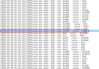
1.Extract all register values before and after the exception to where 0x18h is different by locating them.
0x18 = 481d when the first phenomenon occurs; 0x18 = 5a25 when the second phenomenon occurs;


3.By comparing the chip manual, combined with bit9 bit14 reflect, phy may have entered some kind of training mode, especially when the second problem occurs.Enters sleep-related status.
Bit9: 1b = WUP received from remote PHY when in sleep
Bit14: 1b = Link has not been observed within time programmed in 0x562 once training has started
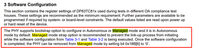
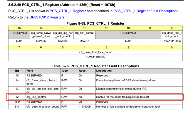
4.The application layer has operated the 0x485 register bit12 to manually control phy linkdown/linkup.However, there is a question about the register bit12:
Bit12: Enable for the entire training/linkage to start
Is Training one of the special modes of the phy chip?Or how do I use this register correctly?XOR How do I properly control phy linkdown/linkup via the registers?

  • Hi Colt,

    Before I give you more details, it feels like both the devices you are using are of different revisions.
    Can you please read register 0x3 on both the devices?

    What is the link partner used? Is it DP83TC812 or a PHY from another vendor?

    Can you please confirm that you are using the initialization register settings mentioned in the app note https://www.ti.com/lit/ml/snla389a/snla389a.pdf ?

    --
    Regards,
    Gokul.

  • The answers to the questions raised are as follows:
    1The value of register 0x3 is a271;
    2The end node is the gateway, using phy on the marvel switch;
    3.For the initialized register settings, the values are shown in the phy_initial_val.txt in the attachment phy_initial_val.rar.


    At present, there are the following questions that need to be answered:
    1 The application layer operation for phy is to modify the value of register 0x485 to 0/1, because the dp83tc812s-q1.pdf documentation shows that bit12 for 0x485 is a link up enabled configuration, but does not explain the setting of the bit value to 0.When the previous problem occurred, there were 0 and 1 modifications to the value of the register 0x485 bit12, resulting in occasional packet blocking problems; can the Ethernet link up/link down state be controlled manually by operation 0x485?

    2.The application layer wants to manually control the link up/link down state by setting the register value, the correct method should be how to operate the register to achieve this effect?


    3 For the www.ti.com/.../snla389a.pdf document mentioned in the link, it describes the bit0 of the register 0x0523 to enable or disable the link up function.However, the dp83tc812s-q1.pdf documentation does not contain any description of the register 0x0523.Can the link up feature be set to on or off to achieve a manually controlled Ethernet link up/link down state by operating the 0x523 address?

    4.For the www.ti.com/.../snla389a.pdf document mentioned in the link, it describes the two modes of the PHY.Autonomous/Managed mode, what do these two modes mean?How do I determine what mode the current PHY is in?And how do you switch between the two modes back and forth?Since the PHY may not have been operated previously, it should be the default Autonomous mode, when in that mode, the operation register 0x485 value,Or do other addresses of the registers have an effect on the PHY function?

    phy_initial_val.rar

  • Hi Colt,

    0x0485[12] can be used to control link up and down. Making this bit 1 enables device to link and making this 0 disables the link.
    After this bit is made 1, PHY will not be ready for communication immediately. Host can only transfer packets after link status is 1.

    Register 0x523 can also be used as used in the initialization settings.

    For Managed/Auto mode, the device will be in Standby state is Managed mode and will be in Normal state in Autonomous mode.
    To use this method, you can use 0x018C = 0x0010 for standby state and 0x018C = 0x0001 for normal state. 

    Regarding the initialization settings, host needs to program these settings post power-up or reset. The log you shared doesn't have these registers. I hope the host is programming these settings for reliable link-up.

    --
    Regards,
    Gokul.

  • Thank you very much for your response, the current testing phenomenon is as follows:
    1.After modification of the register 0x485 bit12, after power-up, although the status of the link can be controlled, However, there is an Ethernet blocking problem; canceling bit12 operation on register 0x485 does not occur;
    After setting the register 0x523 bit1, power-up can also control the status of the link. No Ethernet blocking issues;
    In the light of the above, the following points are raised:
    What is the cause of the Ethernet blocking problem when operating with register 0x485 bit12? What do training/link, training, and link refer to in the description of operation of the register 0x485 bit12? Now, it is assumed that training was started instead of link after setting up, which is causing the problem, so wonder what training is?

    2. In your latest reply, mention that after setting the bit12 for register 0x485 to 1, it will not take effect immediately, can you describe the reason why it does not take effect immediately?


    3.As you mentioned, the host needs to be programmed to initialize after power-up or reset. In a test scenario, the operation of register 0x523 was actually modified after a power-up and the test passed; however, the subsequent work scenario controlled the link state at any time during use. That is, it is possible that no power-up or reset will be performed, and in this case, can the link state be controlled?
    Do you refer to these registers that are not included in the log, 0x523 and 0x18C? Or are there other registers that need to be set apart from these two? If so, what more registers need to be configured (some of the registers in the document are not described at all)? If these registers are not configured, will there be an impact on the reliability of the link?

  • Hi Colt,

    Can you please let me know in detail what ethernet blocking problem means?

    When you control 0x485[12] or 0x523[0] (not bit 1) link goes down. The device will take a maximum of 100ms to link-up again and hence no communication goes through during that time.

    As you mentioned, the host needs to be programmed to initialize after power-up or reset. In a test scenario, the operation of register 0x523 was actually modified after a power-up and the test passed; however, the subsequent work scenario controlled the link state at any time during use. That is, it is possible that no power-up or reset will be performed, and in this case, can the link state be controlled?

    During programming initialization settings, 0x523 is used to block any transmit during the time register settings are written. 
    After programming the initialization settings, 0x523[0] can be used.
    If a reset or power-up is done, initialization settings should be programmed again.

    Post initialization-script, if you use either 0x523 or 0x18C or 0x485, only this filed needs to be programmed again and not the whole set of registers.

    (some of the registers in the document are not described at all)? If these registers are not configured, will there be an impact on the reliability of the link?

    If these initialization settings are not programmed, a reliable link is not achieved across all link partners and conditions.

    --
    Regards,
    Gokul.

  • After operating register 0x485, there are two types of problems (that is, the Ethernet blocking problem I mentioned in my previous question):
    The value of the query register 0x1 is 65h and the status is link up, but the controller does not receive a peer message internally. Internal messages cannot be forwarded. The scene continues and does not automatically resume. Recover after manual write register 0x1F is 8000.
    The value of the query register 0x1 is 61h, the status is link down, and after the link down state lasts for several minutes, the link state may switch to link up. The value of the 0x1 query again changes to 65h, during which communication can be automatically resumed.
    The phenomenon of this Ethernet blocking issue was also described in my initial question.
    The problem remains as follows:
    What causes the above behavior after register 0x485 operation? And what does training and link mean?
    What are all the registers to initialize the settings in order to establish a reliable link?
    I hope you can reply to each of the articles. Thank you!

  • Hi Colt,

    I can check with the team and what is the difference between 0x485 and 0x523 and will let you know.

    --
    Regards,
    Gokul.

  • add a new question,

    When testing a model 812 PHY chip, it was found that the device was shorting a pin to ground or to power, and the bit6 value of register 0x310 was 0, indicating a short circuit; however, In the case of an open circuit, the bit6 value of the acquired register 0x310 is 0, not the expected result of the open circuit, the bit6 value is 1;

  • Hi Colt,

    Can you please share the read value of register 0x310 and 0x1E during this test (i.e., when the wire is open)?

    Can you please confirm that initialization settings mentioned in section 7 of SNLA389 are followed for TDR testing?

    --
    Regards,
    Gokul.