Part Number: DP83TG720S-Q1
Other Parts Discussed in Thread: ETHERNET-SW, DP83TG720EVM-MC,
Hi Team,
Our NXP u-boot cannot initiate this dp83tg720 PHY correctly. I traced the u-boot source code, and it looks like only a dp83867.c (Gigabit ETH) driver file is included in /drivers/net/phy/.
Can you advise on what needs to be reconfigured or added to the driver file pool?
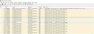
I can dump mii or mdio info in u-boot about our dp83tg720, and send along for your info. Can confirm our T1 PHY is in a live and healthy state. One primary parameter to reconfigure is that PHY address needs to be set to 0x0c.