This thread has been locked.

If you have a related question, please click the "Ask a related question" button in the top right corner. The newly created question will be automatically linked to this question.

SN65DP159: whether or not IIC_CTL of SN65DP159 is blocked by TCA9517A?

Part Number: SN65DP159
Other Parts Discussed in Thread: TCA9517A, TCA9509, TCA9517, TCA6507

Hi, David.Liu:

I have a new finding, and let's continue the below thread:

https://e2e.ti.com/support/interface-group/interface/f/interface-forum/1196577/sn65dp159-no-response-of-sn65dp159-iic-interface-scl-sda_ctl

I connect Aardvark I2C/SPI Host Adapter to IIC chain as below figure shown, and DP159 could be accessed successfully through it . So, I turn to this level shift(TCA9517ADGKR)  and guess this LS

maybe block access of DP159, especially the low level signal which make the DP159 could not identify the device address.

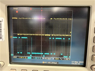
Below figure shown the waveform through this LS without Aardvark I2C/SPI Host Adapter . The low level is close to ~500mv which accord with 0.52mv(VOL) in the datasheet. I can't see the ACK from DP159

Below figure shown the waveform through Aardvark I2C/SPI Host Adapter. The low level is close to ~250mv. Also I can see the ACK from DP159

But, there is a strange point. The MAX VIL for DP159 is 0.3 x VCC which is 0.99v.  Because 0.99v >0.6v(MAX VOL from LS), it should have be OK for access through LS. But it not.

Could you please suggest me another level shift which could be pin to pin compatible with TCA9517ADGKR? 

Thanks in advance!!!

Best regards!

Jason

  • Jason:

        David is on travel, may replay late.

    Regards

    Brian

  • Hi, David.Liu and Brain Zhou:

    I got a new finding yesterday.

    When I replaced TCA9517A with TCA9509, DP159 could give out ACK as below figure shown. As you see, B side's Vol of TCA9509 is close to 0 (TYP 0.1v in datasheet). 

    So, I think the B side' Vol of TCA9517 is too high(close to 0.52v) so that the DP159 couldn't identify its device address, as below figure shown:

    But, as I mentioned in the above my response, there is a very strange point. The MAX VIL for DP159 is 0.3 x VCC which is 0.99v.  Because 0.99v >0.6v(MAX VOL from TCA9517), it should have be OK for access through TCA9517. But it not.

    Could you please help me confirm if B side of TCA9517 could be interfaced with DP159 from the TI official point  of view???

    Thanks in advance!

    Best Regards!

    Jason

  • Hey Jason,

    You are correct- the TCA6507 should be be able to pass a logic LOW (VOL) at 0.6V max since this is below the max VIL (30% of 3.3V) of the DP159. There seems to be a gap with DP159 VIL as both bus repeaters VOL are under the VIL maximum, yet only the TCA9509 works. Are there any external components that are also connected on the bus that isn't included on the block diagram? 

    Can the TCA9509 (the working bus repeater) be a feasible solution for your system requirement? 

    Regards,

    Jack 

  • Jason

    Between the two I2C level shifters, can you zoom into the waveform and measure the setup and hold timing between the SCL and SDA to see if there is a timing difference between the two?

    On the TCA6507, can you also play with the pullup resistors to see if we can get DP159 to ACK?

    Thanks
    David

  • Hi, Jack:

    Yes, there are DP159, Si5324(clock chip) and EEPROM on the B side of TCA9517A as blow figure shown. But I have done test after removing Si5324 and EEPROM from the IIC chain, DP159 also can't give out ACK too. So I connect Aardvark I2C/SPI Host Adapter to the IIC chain on the B side of TCA9517A , this time DP159 could give out ACK. I compare the waveform these two case, and find that The low level of waveform through Aardvark I2C/SPI Host Adapter is close to ~250mv. It is less than the 0.52v output from B side of TCA9517A. So, I turn to look for a pin to pin compatible substitution to replace TCA9517A which' B side could output enough low level. Then TCA9509 is a suitable substitution, and IIC_CTL of DP159 could work normally through it. 

    TCA9517A should have work form the spec point  of view, but it not. Although this time the problem have been resolved through substitution, currently I just want to know why? It will impact chip selection later if not figure it out now.

    Thanks in advance!

    Best Regards!

    Jason

  • Hi, David:

    Nice to see your back ! 

    Please check below two waveform:

    The left is the waveform of B side of TCA9517A ( blue is SCL and green is SDA). The IIC frequency is 100KHz that means period is 10us. You can see that the setup time and and hold time are all close to 5us 

    The right is the waveform of B side of TCA9509 ( blue is SDA and green is SCL). The IIC frequency is 100KHz that means period is 10us. You can see that the setup time and and hold time are all close to 5us 

    I have tried 1K and 10K pullup resistors on the B side of TCA9517A too. They all can't work

    Thanks in advance!

    Best Regards!

    Jason

  • Jason

    I got a TCA9517 EVM and plan to hook it up to the DP159 EVM, let me see if I can duplicate this issue in the lab and then respond back to you.

    Thanks

    David

  • Hi, David:

    Please note that I used TCA9517A , not TCA9517. The main difference between them is the VILC. But I think this difference doesn't impact this problem

    Thanks in advance!

    Best Regards!

    Jason

  • Jason

    Understood, let me set up the two EVM in the lab and then report back on what I find.

    Thanks

    David

  • Jason

    I had the TCA9517A EVM connected to the DP159 EVM as shown below

    But so far I am able to correctly read the DP159 DEV ID using the Aardvark I2C controller.

    Thanks

    David

  • Hi, David:

    Aardvark I2C controller is connected to A side of TCA7517A, and B side of TCA7517A is hooked up to the DP159 EVM, right?

    Could you please provide the waveform of B side of TCA7517A to me?

    Pullup resistors are 10K on the B side of TCA7517A. But the recommended value in the DP159 datasheet is 2.2K. Could you please replace 10K with 2.2K and try again?

    Thanks in advance!

    Best Regards!

    Jason

  • Jason

    Please see the scope capture on the B side with the 10k pullup removed on the B side.

    The Aardvark is on the A side while the B side is connected to the DP159 EVM. Both A and B side are powered with 3.3V.

    Thanks

    David

  • Hi, David:

    Get it ! 

    As below snapshot shown, DP159 does give out ACK which conform to spec (0.99v VILmax ).

    But, it is too strange on my board. I can't explain it. 

    Thank you again!

    Thanks in advance!

    Best Regards!

    Jason

  • Jason

    Is there a way you can duplicate my setup with Aardvark and 3.3V on the A side? This is one difference I see between yours and my setup.

    Thanks

    David

  • Hi, David:

    OK, later on I will try it as your said. 

    BTW,  Si5324(clock chip) could be accessed through TCA9517A as below figure shown. So, I think the A side of TCA9517A should have no problem

    Thanks in advance!

    Best Regards!

    Jason