This thread has been locked.
If you have a related question, please click the "Ask a related question" button in the top right corner. The newly created question will be automatically linked to this question.
Hi team,
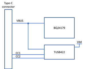
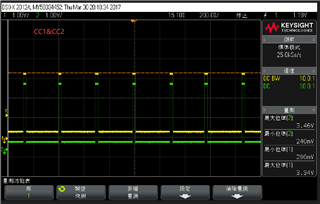
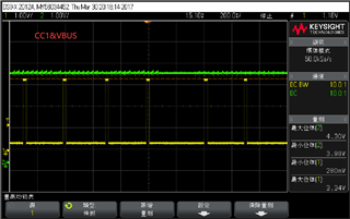
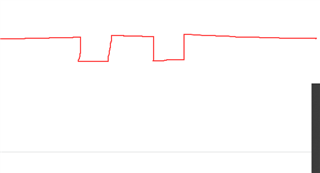
My customer said that they found the period square on the CC1 and CC2 almost 200mV with Vbus 4.5V. And when Vbus went to 4.1V, they still found period square on CC1 and CC2 but the amplitude of wave was 100mV.
They gave me a draft about the square shown below.
Looking forward your reply.
Thanks
NAN
Vbus is from USB connector or rom Vbus switch?
Regards
Brian
Hi Brain,
The Vbus is from the USB connector. Here is how they use.
And the Tusb422 schematic is shown below.
The wave show how the CC1 and CC2 send square wave, when the vbus goes to 4.1V.And when the Vbus is 4.5V, the cc1 and cc2 stay low.
Here is CC1 with VBUS.
So could you please confirm that whether it is normal for TUSB422 to send period square wave on CC1 and CC2? If so, please tell why the TUSB422 has such action.
YOURS
NAN
TUSB422 send period square wave on CC pin when in DRP mode and stay low in UFP mode.
SInce the design is in UFP mode, when VBus below 4.1v, TUSB422 entering DRP mode unexpectedly.
Regards
Brian
Hi Brain,
Thanks for your reply.
As you mentioned "unexpectedly", does it mean that we can not predict whether tusb422 goes into UFP mode or DRP mode? Do you have more details on Vbus detect?
YOURS
NAN
Brain,
The customer set TUSB422 as DRP. When their device connect with customer, their product would set as sink(UFP).
YOURS
NAN
Nan:
Without connect to customer, what CC waveform looks like when VBus is 4.1v and 4.5v?
Regards
Brain
Hi Brain,
The customer is testing. Could you please to have test on the EVM?
Q1,So is that normal for TUSB422 to have such wave?
Q2, Does the tusb422 have such ability to detect the voltage of vbus to change the role in power supply ?Are there registers to change the threshold on tusb422?
Q3 I find registers description in datasheet. Are these registers set to change the threshold about the 4.1V or 4.5V?
YOURS
NAN
Nan:
Q1: As I said before, CC should be low in UFP mode and clk signal in DRP mode.
Q2: it should not change role for just power supply change,
Q: Iff the Vbus is uased as power supply, then threshold may change.
Regards
brian