Part Number: TCA8418
Hi,
I asked this question long ago and somehow i resolved the problem but I lost the solution due to window problem and i am back to the same problem.
I am using the given code that i downloaded from a github. Linked given on the code.
It works fine for me but the last 6 keys, it shows double output as shown in serial monitor data.
/*
 * TCA8418 Driver
 * This code is adapted from the phishman's driver for arduino, https://github.com/phishman/TCA8418
 * The difference is that it is written to be easily ported to another microcontroller
 * Author: Henry Troutman
 */

/*
 * Keyboard PCB Hookup Guide:
 * 1 -> 3.3V
 * 2 -> GND
 * 3 -> SDA
 * 4 -> SCL
 * 5 -> INT_PIN
 * 6 -> RTC_INT (ds3231)
 */

// Arduino I2C Library
#include <Wire.h>

// keyboard Constants
#define KEYBOARD_ADDRESS 0x34
#define KEYBOARD_INT_PIN 1
#define KEYBOARD_STATE_REGISTER 0x04
#define KEYBOARD_FLAG_REGISTER 0x02
#define KEYBOARD_KEY_DOWN 0x80
#define KEYBOARD_KEY_MASK 0x7F


// configuration commands (configures the 3x9 matrix as inputs with pullups, interrupts ...
// For more information look at the code in the repo linked above
const uint8_t KEYBOARD_CONFIG_COMMANDS[] = {0x1D,0x07,0x1E,0xFF,0x1F,0x01,0x01,0xB9,0x02,0x09};


// Define our functions before use
void keyboard_configure(void);
void keyboard_clearFlag(void);
uint8_t keyboard_getState(void);

// keyInt allows our event to ultimately be handled in the loop
volatile bool keyInt = false;

void setup() {
  Serial.begin(9600);
  Wire.begin();
  keyboard_configure();
  pinMode(KEYBOARD_INT_PIN,INPUT); // There is an external pullup on the pin

  // Set up a falling edge pin interrupt on pin 1
  attachInterrupt(digitalPinToInterrupt(KEYBOARD_INT_PIN), keyboard_ISR, FALLING);
}

void loop() {
  if(keyInt)
  {
    uint8_t key_code = keyboard_getState(); // Get first keycode from FIFO
    if(key_code & KEYBOARD_KEY_DOWN)
    {
      // This is where we can write to a screen or handle control keys
      Serial.print(key_code&KEYBOARD_KEY_MASK); // print the keycode
      Serial.print(",");
    }
      keyInt = false;
      keyboard_clearFlag();
    delay(100);
  }
}

void keyboard_configure(void){
  for(uint8_t i = 0;i < 9;i+=2){
    Wire.beginTransmission(KEYBOARD_ADDRESS);
    Wire.write(KEYBOARD_CONFIG_COMMANDS[i]);
    Wire.write(KEYBOARD_CONFIG_COMMANDS[i+1]);
    Wire.endTransmission();
  }
}
uint8_t keyboard_getState(void){
  uint8_t key;
  Wire.beginTransmission(KEYBOARD_ADDRESS);
  Wire.write(KEYBOARD_STATE_REGISTER);
  Wire.endTransmission();
  Wire.requestFrom(KEYBOARD_ADDRESS, 1);    // request 1 bytes from slave device 0x34
  while (Wire.available())
  { // slave may send less than requested
    key = Wire.read(); // receive a byte as character
  }
  return key;
}
void keyboard_clearFlag(void){
  Wire.beginTransmission(KEYBOARD_ADDRESS);
  Wire.write(KEYBOARD_FLAG_REGISTER);
  Wire.write(0x0F);
  Wire.endTransmission();
}
void keyboard_ISR(void){
  keyInt = true;
}

/*
I2C Command Summary

Setup board (3x9 keypad)
write to Register, value
            0x1D, 0x07
            0x1E, 0xFF
            0x1F, 0x01
            0x01, 0xB9
            0x02, 0x09

To get keys
read 1 byte from 0x04

To clear interrupt flag
write to register,value
            0x02, 0x0F

 */
I have two request if you can help me with it.
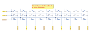
- Assign number in same sequence for SW1 to SW9 as for SW10 to SW18. For example, instead of 21 to SW1, it should be 1 for SW1. The sequence of SW10 to SW18 is perfect.
- Assign a single unique number from SW19 to SW27 instead of double number
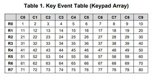
Serial Monitor Data
21 to 29 for SW1 to SW9 press
11 to 19 for SW11 to SW18 press
So far it is acceptable to me until it give me a unique ID.
The problem starts when i press SW19 then it generate a pair output i.e. 1,2
SW20 2,3
SW21 3,4 and so on
I need to know where i am doing wrong for last 9 switches.
I am using 3X9 keypad matrix.