This thread has been locked.

If you have a related question, please click the "Ask a related question" button in the top right corner. The newly created question will be automatically linked to this question.

DS90UB960-Q1: Timing shift in MIPI-CSI2 frame (vertical) and line (horizontal) sync packets

Part Number: DS90UB960-Q1
Other Parts Discussed in Thread: DS90UB953-Q1

Dear team,

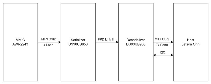
We are using DS90UB953-Q1 and DS90UB960-Q1 as SerDes to transmit the video stream from a sensor with MIPI CSI-2 interface. We only connect one sensor and set the strean output to DS90UB960 CSI2 port0.

However, we cannot read the video stream from the termination side and we got “LP sequence Error” from termination's D-PHY.

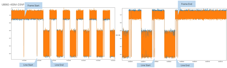
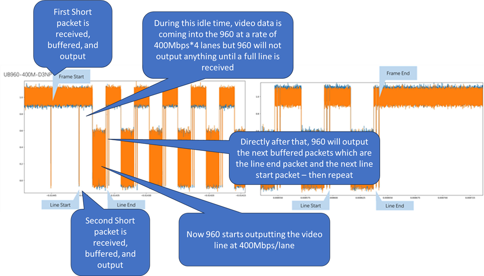
We probed the waveform on the lanes between the sensor and Orin, we found that the time specifications in the long and short packets of CSI-2 are consistent with the requirements in the CSI2 manual. However, compared to the CSI2 waveform sent by the sensor, the timing of the frame and line sync packets from 960 CSI2 output port appears to have shifted.

The frame end packet did not appear at the end of the frame data transmission, but appear at the place where very close to the start of the next frame. And the line start/end packet also seems strange.

There is always a long LP status hold after the line start packet is sent, before the line data. However, the line end packet will appear as soon as the line data has finished.

The sync packets in the waveform of the sensor CSI2 output port are correct, but become strange after SerDes in the DS90UB960 output, which confused us.

I think something must have gone wrong when processing the SerDes, however we haven't found any errors according to the registers both in SerDes.

Could you please give us an idea of how to overcome the above problem?

Thanks a lot,

Lee

  • Hi Lee,

    Monday, May 29th is a US public holiday, we will resume activity on this thread beginning Tuesday. Thanks for your patience. 

    Regards, 
    Logan

  • Hi Lee,

    Can you provide the waveforms and register dump in a good and bad case?

    Are you see this on one or multiple setup?

    Glenn 

  • Hi Glenn,

    Sorry for taking so long to reply.

    Please check the attachment below:

    waveform:

    registers:

    UB953:
         0  1  2  3  4  5  6  7  8  9  a  b  c  d  e  f
    00: 30 00 73 4b 00 18 41 28 fe 1e 10 7f 7f 06 34 00
    10: 00 00 00 00 00 20 18 3c 80 62 62 62 00 00 00 00
    20: 00 00 00 00 00 02 00 00 67 33 01 00 00 00 00 00
    30: 00 20 09 04 00 10 00 64 00 00 00 00 00 00 00 00
    40: 00 00 00 00 00 00 00 00 00 00 00 00 00 00 00 00
    50: 20 c0 45 00 00 00 00 00 07 07 07 00 00 00 00 00
    60: 00 2a 00 10 0f 8b 01 44 00 00 00 00 00 00 00 00
    70: 00 00 25 00 00 00 00 00 00 00 e4 00 00 00 00 00
    80: 00 00 00 00 00 00 90 00 00 00 00 00 05 00 00 00
    90: 32 e3 64 01 00 00 00 00 00 00 03 02 00 00 00 0f
    a0: 00 0d 0e 0d 0e 10 42 10 10 10 03 01 00 00 00 00
    b0: 02 21 00 00 00 00 00 00 00 00 00 00 00 00 00 00
    c0: 00 00 00 00 00 00 00 00 00 00 00 00 00 00 00 00
    d0: 00 00 00 00 00 00 00 00 00 00 00 00 00 00 00 00
    e0: 00 00 00 00 00 00 00 00 00 00 00 00 00 00 00 00
    f0: 5f 55 42 39 35 33 00 00 00 00 00 00 00 00 00 00
    
    UB960:
         0  1  2  3  4  5  6  7  8  9  a  b  c  d  e  f
    00: 64 00 1e 40 d0 01 00 fe 1c 10 7a 7a 01 00 02 ff
    10: 00 00 00 00 00 00 00 00 80 61 a8 e3 dd 00 04 04
    20: e0 03 00 01 00 00 00 00 00 00 00 00 00 00 00 00
    30: 00 00 01 41 01 01 00 00 00 00 00 00 00 00 00 00
    40: 00 a9 71 01 00 00 20 00 00 00 00 12 01 03 04 62
    50: 9f 00 00 03 00 00 00 00 5a 00 00 30 80 a8 50 00
    60: 00 00 00 00 00 a8 c0 00 00 00 00 00 00 7c 8a 88
    70: 2b 2c 00 02 00 10 00 c5 00 01 00 00 00 f1 00 00
    80: 00 00 00 00 00 00 00 00 00 00 00 00 00 00 00 00
    90: 60 eb 00 00 ff ff 00 00 00 00 00 00 00 00 00 00
    a0: 00 00 00 00 00 1d 00 00 00 00 00 00 00 00 00 00
    b0: 1c 13 1f 08 25 00 18 00 9c 33 83 74 80 00 00 00
    c0: 00 00 00 00 00 00 00 00 00 00 00 00 00 00 00 00
    d0: 00 43 94 27 60 f2 00 02 00 01 00 00 00 00 00 00
    e0: 00 00 00 00 00 00 00 00 00 00 00 00 00 00 00 00
    f0: 5f 55 42 39 36 30 00 00 00 00 00 00 00 00 00 00

    We also tried 800MHz mode, there is still an blank LP status before the line data, but the line end packet still appears once the line data transmission ends. And the LP status between the line end and the next line start becomes longer compared to the 400MHz case.

    Best,

    Lee

  • Hi Lee, 

    I will review your data and provide feedback next week.

    Glenn 

  • Hi Lee,

    1. In 960 Reg 0x1F, can you try setting bit[2] REF_CLK_MODE back to the default value of 0?
    2. Just to confirm, do the CSI-2 settings on the 953 match what is coming from the imager? And do the CSI-2 settings on the 960 match what the SOC is expecting? I noticed that 960 is configured for non-continuous clock while 953 is configured for continuous clock, so I want to double check that this is the correct configuration. 
    3. Can you try turning off the imager and use 953 patgen instead?

    Regards,

    Cindy 

  • Hi Cindy,

    Thank you for your help.

    1.The problem still exists after we changed the registers.

    Registers now:

    UB953
         0  1  2  3  4  5  6  7  8  9  a  b  c  d  e  f
    00: 30 00 73 58 00 03 00 00 fe 1e 10 7f 7f 00 00 00
    10: 00 00 00 00 00 20 18 3c 80 62 62 62 00 00 00 00
    20: 00 00 00 00 00 02 00 00 67 33 01 00 00 00 00 00
    30: 00 20 09 04 00 10 00 64 00 00 00 00 00 00 00 00
    40: 00 00 00 00 00 00 00 00 00 00 00 00 00 00 00 00
    50: 20 c0 45 00 00 00 00 00 07 07 07 00 00 00 00 00
    60: 00 2a 00 10 0f 8b 00 00 00 00 00 00 00 00 00 00
    70: 00 00 25 00 00 00 00 00 00 00 e4 00 00 00 00 00
    80: 00 00 00 00 00 00 90 00 00 00 00 00 05 00 00 00
    90: 32 e3 64 01 00 00 00 00 00 00 03 02 00 00 00 0f
    a0: 00 0d 0e 0d 0e 10 42 10 10 10 03 01 00 00 00 00
    b0: 02 21 00 00 00 00 00 00 00 00 00 00 00 00 00 00
    c0: 00 00 00 00 00 00 00 00 00 00 00 00 00 00 00 00
    d0: 00 00 00 00 00 00 00 00 00 00 00 00 00 00 00 00
    e0: 00 00 00 00 00 00 00 00 00 00 00 00 00 00 00 00
    f0: 5f 55 42 39 35 33 00 00 00 00 00 00 00 00 00 00
    
    UB960
         0  1  2  3  4  5  6  7  8  9  a  b  c  d  e  f
    00: 64 00 1e 40 d0 01 00 fe 1c 10 7a 7a 01 00 02 ff
    10: 00 00 00 00 00 00 00 00 80 61 a8 e3 dd 00 04 02
    20: e0 03 00 01 00 00 00 00 00 00 00 00 00 00 00 00
    30: 00 00 01 03 00 01 00 00 00 00 00 00 00 00 00 00
    40: 00 a9 71 01 00 00 20 00 00 00 00 12 01 03 04 64
    50: 00 00 00 03 00 00 00 00 5e 00 00 30 80 a8 50 00
    60: 00 00 00 00 00 a8 c0 00 00 00 00 00 00 7c 8a 88
    70: 2b 2c 00 02 00 10 00 c5 00 01 00 00 00 00 00 00
    80: 00 00 00 00 00 00 00 00 00 00 00 00 00 00 00 00
    90: 4b 08 00 00 ff ff 00 00 00 00 00 00 00 00 00 00
    a0: 00 00 00 00 00 1d 00 00 00 00 00 00 00 00 00 00
    b0: 1c 13 1f 08 25 00 18 00 9c 33 83 74 80 00 00 00
    c0: 00 00 00 00 00 00 00 00 00 00 00 00 00 00 00 00
    d0: 00 43 94 02 60 f2 00 03 00 01 00 00 00 00 00 00
    e0: 00 00 00 00 00 00 00 00 00 00 00 00 00 00 00 00
    f0: 5f 55 42 39 36 30 00 00 00 00 00 00 00 00 00 00

    2. We tried UB953 PatGen mode with the script below, the line sync short packet disappeared, so we don't know if the problem exists or not.

    static int init_pattern_generator(struct regmap *map)
    {
        int err = 0;
    
        TRY(err, regmap_write(map, 0xB0, 0x02));    // IA_AUTO_INC=1
        //TRY(err, regmap_write(map, 0xB1, 0x01));    // PGEN_CTL
    
        //TRY(err, regmap_write(map, 0xB2, 0x01));    // PGEN_ENABLE=1
        TRY(err, regmap_write(map, 0xB1, 0x02));    // PGEN_CFG
        TRY(err, regmap_write(map, 0xB2, 0x33));    // BLOCK_SIZE=3 NUM_CBARS=3(8 Color Bars)
        TRY(err, regmap_write(map, 0xB2, 0x2A));    // PGEN_CSI_DI  (Virtual Channel:0, Data Type:0x2A)
        TRY(err, regmap_write(map, 0xB2, 0x10));    // PGEN_LINE_SIZE1   0x780=1920 0x1000=4096
        TRY(err, regmap_write(map, 0xB2, 0x00));    // PGEN_LINE_SIZE0
        TRY(err, regmap_write(map, 0xB2, 0x02));    // PGEN_BAR_SIZE1    0xF0=240
        TRY(err, regmap_write(map, 0xB2, 0x00));    // PGEN_BAR_SIZE0
        TRY(err, regmap_write(map, 0xB2, 0x02));    // PGEN_ACT_LPF1     0x438=1080
        TRY(err, regmap_write(map, 0xB2, 0x00));    // PGEN_ACT_LPF0
        TRY(err, regmap_write(map, 0xB2, 0x02));    // PGEN_TOT_LPF1     0x465=1125 0x200=512
        TRY(err, regmap_write(map, 0xB2, 0x00));    // PGEN_TOT_LPF0
        TRY(err, regmap_write(map, 0xB2, 0x4C));    // PGEN_LINE_PD1     2963   0x4C4B=19531
        TRY(err, regmap_write(map, 0xB2, 0x4B));    // PGEN_LINE_PD0
        TRY(err, regmap_write(map, 0xB2, 0x0A));    // PGEN_VBP
        TRY(err, regmap_write(map, 0xB2, 0x0A));    // PGEN_VFP
        TRY(err, regmap_write(map, 0xB2, 0xAA));    // PGEN_COLOR0
        TRY(err, regmap_write(map, 0xB2, 0x33));    // PGEN_COLOR1
        TRY(err, regmap_write(map, 0xB2, 0xF0));    // PGEN_COLOR2
        TRY(err, regmap_write(map, 0xB2, 0x7F));    // PGEN_COLOR3
        TRY(err, regmap_write(map, 0xB2, 0x55));    // PGEN_COLOR4
        TRY(err, regmap_write(map, 0xB2, 0xCC));    // PGEN_COLOR5
        TRY(err, regmap_write(map, 0xB2, 0x0F));    // PGEN_COLOR6
        TRY(err, regmap_write(map, 0xB2, 0x80));    // PGEN_COLOR7
        TRY(err, regmap_write(map, 0xB2, 0x00));    // PGEN_COLOR8
        TRY(err, regmap_write(map, 0xB2, 0x00));    // PGEN_COLOR9
        TRY(err, regmap_write(map, 0xB2, 0x00));    // PGEN_COLOR10
        TRY(err, regmap_write(map, 0xB2, 0x00));    // PGEN_COLOR11
        TRY(err, regmap_write(map, 0xB2, 0x00));    // PGEN_COLOR12
        TRY(err, regmap_write(map, 0xB2, 0x00));    // PGEN_COLOR13
        TRY(err, regmap_write(map, 0xB2, 0x00));    // PGEN_COLOR14
        TRY(err, regmap_write(map, 0xB2, 0x00));    // Reserved
    
        return err;
    }
    

    Best,

    Lee

  • Hi Lee,

    I do not see any issues with the patgen code or the register dump. I did notice that you changed the 960 clock mode from non-continuous to continuous. Just to make sure, is the SOC configured to recognize the CSI-2 settings coming from the 960? Is the SOC still reporting errors when you use patgen?

    Regards,

    Cindy

  • Hi Cindy,

    Thanks for your reply.

    1.

    Errors have changed compared to the error log we ever shared in Guo's post, please check the latest one:

    kworker/4:0-35      [004] ....    85.074410: rtcpu_nvcsi_intr: tstamp:3536462637 class:GLOBAL type:PHY_INTR0 phy:0 cil:0 st:0 vc:0 status:0x00000088
    kworker/4:0-35      [004] ....    85.074414: rtcpu_vinotify_event: tstamp:3537216644 cch:0 vi:0 tag:CHANSEL_PXL_SOF channel:0x23 frame:0 vi_tstamp:113181059520 data:0x0000000000000001
    kworker/4:0-35      [004] ....    85.130411: rtcpu_vinotify_event: tstamp:3537893477 cch:0 vi:0 tag:CHANSEL_PXL_EOF channel:0x23 frame:0 vi_tstamp:113204070464 data:0x0000000001ff0002
    kworker/4:0-35      [004] ....    85.130414: rtcpu_vinotify_event: tstamp:3537893904 cch:0 vi:0 tag:FE channel:0x00 frame:0 vi_tstamp:113204072256 data:0x0000000000000020
    kworker/4:0-35      [004] ....    85.130414: rtcpu_vinotify_event: tstamp:3537894056 cch:0 vi:0 tag:CHANSEL_SHORT_FRAME channel:0x01 frame:0 vi_tstamp:113204072288 data:0x0000200000000000
    kworker/4:0-35      [004] ....    85.298558: rtcpu_vinotify_error: tstamp:3543159065 cch:0 vi:0 tag:CHANSEL_NOMATCH channel:0x01 frame:0 vi_tstamp:113381066048 data:0x0000000000000549

    Errors above meaning:

    1. PHY_Interrupt0
    LP sequence error detected on data lane [A/B]0
    LP sequence error detected on data lane [A/B]1
    2. PIXEL_SOF
    The first pixel in a frame that is not that of an embedded type
    3. PIXEL_EOF
    The last pixel in a frame that is not that of an embedded type
    4. CsimuxFrameError_Regular
    VPR state from fuse block    [ 3]: 0
    A frame end has been found on a regular mode stream.
    5.ChanselPixShort
    Channel 35
    This can happen for three reasons: PIXEL_SHORT_FRAME: FE packet arrives before last expected pixel of the uncropped image; PIXEL_EMPTY_FRAME: FE packet arrives before cropped pixels other embedded data been received; PIXEL_OPEN_LINE: A pixel line has been opened with line start but FE packet arrives before line end ever arrives.
    6. ChanselNoMatch
    -NO_MATCH                    [ 0]: 1
    The non-embedded data packet does not match any configured channels at all

    We had problems with the SOC configuration, but after contacting NVIDIA, we believe the configurations now are all correct. Maybe you can help us to check it again?

    Because of the sync packet and voltage issues, we cannot rule out the possibility that there are still errors in the SerDes.

    2.

    I also post the device layout map here, which may be useful.

    Thanks a lot.

    Best,

    Lee

  • Hi Lee, 

    I reviewed the register dump and patgen script that was shared earlier. 

    I found an error in the following snippet: 

    TRY(err, regmap_write(map, 0xB2, 0x02)); // PGEN_ACT_LPF1 0x438=1080
    TRY(err, regmap_write(map, 0xB2, 0x00)); // PGEN_ACT_LPF0
    TRY(err, regmap_write(map, 0xB2, 0x02)); // PGEN_TOT_LPF1 0x465=1125 0x200=512
    TRY(err, regmap_write(map, 0xB2, 0x00)); // PGEN_TOT_LPF0

    When setting the total lines per frame, the vertical blanking (vertical front porch, vertical back porch, and vertical sync) must be added to the total lines per frame. In this case the active lines per frame and totals are the same. However, later on the vertical front porch and back porch are 12 each. PGEN_TOT_LPF0 should then be a minimum of 0x14. Would you be able to change these values and retest? 

    Additionally, in the 960 register dump, 0xA5 which measures the REFCLK frequency in MHz reads as 0x1d (29 MHz). Can you confirm an oscillator with 25Mhz frequency is being used?

    Best,

    Zoe

  • Lee,

    I think what you are seeing is actually expected behavior. Let me try to explain:

    Architecturally, the 960 uses a line buffer inside for the received CSI-2 data. The 960 will wait until it has received one complete short or long CSI-2 packet before forwarding the packet through the CSI-2 output. In the scope shots you can see this happening:

    In general, CSI-2 as a protocol does not require discrete DPI timing for horizontal timing signals which is why architecturally this is allowed. If you actually want to get discrete line start/line end timing in your application (which it seems like is your goal from the usage of line start/line end packets). You would need to increase the CSI-2 speed of the 960 >> than the CSI-2 speed of the sensor. That way the effect of the 960 having to wait to buffer a video line would be minimized. Even then it may not be possible depending on your horizontal blanking timing from the sensor. There would need to be enough time in the horizontal front porch of the video signal for the 960 to send an entire video line out and be ready to forward the line end packet. The 960 has a maximum transmitter speed of 1.6Gbps/lane so you would need to calculate how long it takes to send one video line at 1.6Gbps/lane and compare that against the horizontal front porch time in us to see which is smaller. 

    Best Regards,

    Casey 

  • Hi Zoe, thank you for your information, I will check the PG mode scripts.

    Hi Casey, thanks for your kind explanation. We were also wondering if the voltage level is also expected during HS transmission?

    We probed it directly from the UB960 CSI output pin, it seems does not match the MIPI standard(150-250mV).

    As long as the voltage is as expected, we can be confident that all is well in the SerDes.

    Best,

    Lee

  • Lee,

    Is the CSI-2 RX active and applying dynamic termination to the interface? The HSTX transmit voltages for DPHY rely on the sink providing termination during the HS portion of the packet so it looks to me like your CSI-2 RX may not be applying termination. Although the probe setup also seems odd because you appear to be getting voltages swinging below 0V too which is not real. You may also have a probing issue 

    Best Regards,

    Casey

  • Hi Casey, you are right, we tried using another oscilloscope now there is no voltage below 0V while the HS voltage is still above the standard.

    Since some of the error messages were prompted by Jetson Orin, we think that the receiver is already activated.

    The HSTX transmit voltages for DPHY rely on the sink providing termination during the HS portion of the packet

    By these words, you mean that the voltages are dependent on the configurations in the receiver?

    We don't know what "applying dynamic termination to the interface" means, can you elaborate?

    Best,

    Lee

  • Jim,

    MIPI CSI-2 D-PHY physical interface uses a dynamic termination scheme. You can study more about the physical interface here for example:

    https://download.tek.com/document/61W_25772_0_HR.pdf

    So during the HS portion of the waveform, the receiver (Orin) will terminate the signal 100 ohm differentially. If the receiver is not active, then the signals will show higher amplitude. First of all, please make sure that the Orin is set to DPHY mode instead of DPHY. You may also need to verify that the receiver is configured to receive data a 400Mbps/lane rate. 

    Also make sure that in the 960 since you are using 400Mbps/lane that you program these extra settings from section 7.4.19 of the datasheet to ensure that the timing is correct:

    Best Regards,

    Casey 

  • Additionally, in the 960 register dump, 0xA5 which measures the REFCLK frequency in MHz reads as 0x1d (29 MHz). Can you confirm an oscillator with 25Mhz frequency is being used?

    Hi Zoe,

    Thank you for your help.

    We confirmed that the 25MHz freq is used for REFCLK pin, but the value in 0xA5 swings from 0x1B~0x1D(27-29) when read in different time.

    What does this mean?

    Best,

    Lee

  • Hi Casey, thank you for the professional explain, we found the voltage did get normal when we run the script to read the stream on the NVIDIA Orin side.

    Best,

    Lee