This thread has been locked.

If you have a related question, please click the "Ask a related question" button in the top right corner. The newly created question will be automatically linked to this question.

TCA9535: Doubt Regarding switch interface with I/O Expander.

Part Number: TCA9535

Hi sir,

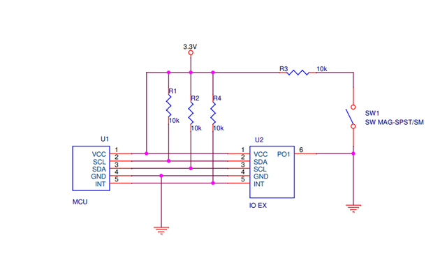
We interface the TCA9535 with LPC55S16 and Configuring the PORT 0 as Input. A switch is connected in P0_1 pin of TCA9535 (Where the switch has verified in both Pull-up and Pull-down). I want to identify the instant of switch press. But there is no change in INT pin status to identify the change in  IO pin. How to identify the change in status of INPUT pin and how we can utilize INT pin kindly navigate us

  • Please show the schematic and your code.

  • Here I attached the Schematic and Code.

    Data_Read.txt
    Fullscreen
    1
    2
    3
    4
    5
    6
    7
    8
    9
    10
    11
    12
    13
    14
    15
    16
    17
    18
    19
    uint32_t i2c_dataread(uint16_t addrs, uint16_t byte_val)
    {
    uint8_t addrs_count = 2, re_read_limit = 0;
    uint8_t Read_Write_Error = 0;
    uint8_t byte_count = 0;
    uint8_t re_write_limit = 0; //For re-writing address byte
    uint32_t read_value = 0, hold_time = 0;
    uint8_t data_byte[4] = {0, 0, 0, 0}, addr_byte[2] = {0, 0};
    //addr_byte[0] =(addrs >> 8) & 0xFF;
    addr_byte[0] =(addrs >> 0) & 0xFF;
    if((addrs >= 65535) && (byte_val > 1))
    {
    Read_Write_Error = 1;
    }
    i2c_start(WRITE_BIT);
    XXXXXXXXXXXXXXXXXXXXXXXXXXXXXXXXXXXXXXXXXXXXXXXXXX

  • Vignesh,

    Your schematic shows PO1 tied directly to GND. Pressing the switch would never change the input status if it is configured this way. 

    You would need to tie the PO1 pin above the switch instead of below it like it currently is.

    -Bobby

  • Hi BOBBY,

    Above schematic wrongly mentioned the resistor connected with Switch.Newly attached schematic represents excat correction between I/O Expander and Micro-controller.

  • The schematic looks OK (disregarding the missing decoupling capacitor).

    That code is just a function that reads a byte from a register, but this function is never called. Which register are you trying to read? Does the input port register show a change in bit 0?

    Please show how you are initializing the registers.

  • Hi Vignesh,

    In addition to Clemens' comments, have you been able to verify that an interrupt is occurring on /INT via scope capture? Attempt to force P01 high to VCC and check on the o-scope to see if /INT pin drives LOW. If from a scope capture you can see the TCA9535 flagging an interrupt, then the error would most likely exist in the code. 

    Regards,

    Tyler

  • Hi Tyler,

          Thanks for the reply. We observe the status of INT in scope while key-press but there is no changes in INT pin. We connected a key on P01,  while keypress we want to know instant of key-press to made changes in controller.

  • Hi Vignesh,

    If you confirmed that the /INT pin is not being driven LOW by a change on P01 via scope captures, then there is no way for the MCU to know if an interrupt has occurred, and does not service the interrupt. I think first we need to solve the issue on why the TCA9535 is not triggering an interrupt with change on P01. 

    Have you tried a power on reset for the device and then re-check to see if a switch press on P01 will cause an interrupt? Default state of the TCA9535 is that all p-port pins are set to input. There is no interrupt masking on this device, so a change in state on the input will cause an interrupt to occur on /INT. 

    Have you confirmed that the physical switch actually works? When you press the switch, is P01 pulled to GND on the o-scope?

    Regards,

    Tyler

  • I was checked with your scenario.when I was pressed the switch the interrupt pin goes low.But after some time I was changing the some connection and rearranged the same scenario I was unable to got the interrupt in the pin.What is the reason behind this. 

  •  Hi,

    I got the Interrupt signal Like this.Below I was attached the image of Digital Oscilloscope.Please reply whether the interrupt was generating like this.

  • Hi Vignesh,

    But after some time I was changing the some connection and rearranged the same scenario I was unable to got the interrupt in the pin.What is the reason behind this. 

    This description is very vague. You say that some connections were changed and rearranged, but these changes caused the interrupt pin not to work correctly as before. What changes did you make? 

    The scope capture that you provided looks like there is a signal on an input pin that fluctuates between HIGH and LOW logic values, causing an interrupt to be asserted then de-asserted because the input pin goes back to its original state. 

    Please be more specific on the changes you made to your system that caused this behavior. A schematic might be helpful here. 

    Regards,

    Tyler