This thread has been locked.

If you have a related question, please click the "Ask a related question" button in the top right corner. The newly created question will be automatically linked to this question.

THVD8000: Support for Error operation of OOK communication in low temperature

Part Number: THVD8000
Other Parts Discussed in Thread: THVD8010

The contents below are about performing OOK operation at -40℃, and we request technical support for the operation.


The two waveforms below are measured from one communication packet.


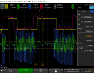
1. Abnormal waveform
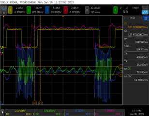
2. Normal waveform


Waveform description

Yellow: Master Rx, Green: Master A-B, Red: Slave Tx, Blue: Slave A-B


The support request is to error operation and normal operation in the part of the oscillating (58 kHz and 104kHz) after the ON/OFF keying (500 kHz).

  1. Request technical support for the reason for error operation at 58 kHz.
  2. Request technical support for the reason for normal operation at 104 kHz.
  • We use OOK frequency is 500kHz and UART communication frequency is 38400bps.

  • Hi Hojun,

    Thanks for reaching out.

    Can you possibly share the THVD8000 schematic and answer the following questions:

    1. Schematic if possible - it looks like there is noise on the bus and that can originate from an unoptimized schematic. 

    2. How many THVD8000 Nodes are in the system? 

    3. What is the length of the bus from end to end.

    4. If you have more than 2 communication nodes on the bus - what network topology are you using. 

    5. If you have more than 2 communication nodes on the bus and you are not using daisy chain - what is the longest unterminated stub-length. 

    It looks like there is noise on the bus - we don't specify the frequency of a logic 1 - as this is the "OFF" part of the OOK modulation - so ideally it should be 0V with no frequency. It does seem there is common mode noise on the bus as well - depending on the schematic it may be fixed through slight alterations - and potentially EMC friendly components such as common mode chokes. I don't really see a huge concern on the the THVD8000 itself at the moment as it seems like the noise is causing the glitch bit. 

    The more information you are able to provide about the system the better chances I have to diagnose the issue. Currently it seems either there could be an impedance mismatch or common mode noise is being coupled in from elsewhere in the system - both of these issues are generally pretty fixable. 

    Right now I am leaning towards three possible solutions:

    1. If there is an impedance mismatch due to components or network topology - this can be fixed by adjusting the system component values to dampen the noise/reflections.

    2. Adding filtering components such as a split termination and/or common mode choke will help reduce noise as well.

    3. Switching to the THVD8010 with a modulation frequency of 300KHz. While running 38.4kbps is technically greater than 1/10th of the modulation frequency - its not off by that much. This device is meant for noisy environments - and based on the noise waveform that you have shown the THVD8010 wouldn't have the false glitch as it has higher thresholds - it is more noise immune. The draw-back is that your duty cycle distortion will no longer be capped to +/-2% and can instead be higher. Generally speaking +/-2% DCD is the cap for a data-rate / modulation frequency ratio of 1/10  and +/-4% for a data-rate/modulation frequency ratio of 1/5. So most likely the system will be bounded by ~+/-3% DCD worst case - we don't guarantee this but it should be a pretty good conservative approximation- so there may be some more jitter on the signal but at the benefit of a more noise resistant part. The THVD8010 is pin to pin with the THVD8000. This might be the simplest solution - but it does have the draw back of the potential of increased jitter for the output UART signal. 

    Please let me know!

    Best,

    Parker Dodson

  • Answer for your questions:

    1. Schematic if possible - it looks like there is noise on the bus and that can originate from an unoptimized schematic. 

    2. How many THVD8000 Nodes are in the system?  → 1 on 1 systems

    3. What is the length of the bus from end to end. → Length is 300m.

    4. If you have more than 2 communication nodes on the bus - what network topology are you using. → 1 on 1 systems

    5. If you have more than 2 communication nodes on the bus and you are not using daisy chain - what is the longest unterminated stub-length. 

        → 1 on 1 systems

    I understand the answer to the following. However, shouldn't OOK communication recognize areas of frequencies other than 500 kHz as low signals?

    -------------------------------------------------------------------------------------------------------------------------------------------------------------------------------------------------------------

    Right now I am leaning towards three possible solutions:

    1. If there is an impedance mismatch due to components or network topology - this can be fixed by adjusting the system component values to dampen the noise/reflections.

    2. Adding filtering components such as a split termination and/or common mode choke will help reduce noise as well.

    3. Switching to the THVD8010 with a modulation frequency of 300KHz. While running 38.4kbps is technically greater than 1/10th of the modulation frequency - its not off by that much. This device is meant for noisy environments - and based on the noise waveform that you have shown the THVD8010 wouldn't have the false glitch as it has higher thresholds - it is more noise immune. The draw-back is that your duty cycle distortion will no longer be capped to +/-2% and can instead be higher. Generally speaking +/-2% DCD is the cap for a data-rate / modulation frequency ratio of 1/10  and +/-4% for a data-rate/modulation frequency ratio of 1/5. So most likely the system will be bounded by ~+/-3% DCD worst case - we don't guarantee this but it should be a pretty good conservative approximation- so there may be some more jitter on the signal but at the benefit of a more noise resistant part. The THVD8010 is pin to pin with the THVD8000. This might be the simplest solution - but it does have the draw back of the potential of increased jitter for the output UART signal. 

    -------------------------------------------------------------------------------------------------------------------------------------------------------------------------------------------------------------

  • Hi Hojun,

    The quality factor of the bandpass internal to the receiver is very low. This means that while the internal bandpass filter changes based on frequency setting resistor - its pass band is going to be large - typically larger than the signal. So even though you set your frequency to 500KHz it most likely would still see data at lower frequencies. The big reason the quality factor is low is because: 1) the carrier frequency has a +/-25% tolerance + a 30KHz spread spectrum clocking signal applied so each frequency in the possible output needs to be able to pass through the filter. 2) It is a pulse train so the filter needs too be able to capture the fundamental frequency + lower harmonics to avoid too much attenuation in the needed range. So there could be attenuation at that lower end - but I don't think it will be enough to prevent a glitch - the THVD8000 thresholds are relatively low - above 225mV and you will get a high on the output. 

    A point to point system as you have indicated at 300 meters long - there are a few considerations:

    1. The system needs to be terminated - each THVD8000 should have a 120 Ohm resistor between A and B (since there is only two nodes on the bus) 

    2. The cabling should have a characteristic impedance of ~120 Ohms to prevent reflections - if you can have a shielded cable that may be beneficial to blocking noise. 

    3. In an ideal system that is 300m long using a 500KHz modulation signal with an system setup (120 Ohm twisted pair cabling is what is tested for the following graph). You are maxing out at about 120m (400ft) 

    To read this graph you need to double you modulation frequency - as this is using standard RS-485. I.e. the modulation frequency of 500KHz is equivalent to running a 1Mbps data stream on standard RS-485 - your data rate doesn't matter as much for the THVD8000 when looking at bus length.

    What this chart says is that at 500KHz modulation frequency (shown as 1Mbps) to avoid signal jitter the max bus length should be 400feet (120m) - for a 300 meter bus (~1000ft)  - you will be adding about 5% jitter to your signal. If you actually slow down your system to 300KHz modulation frequency the jitter added from the system + the jitter added from the duty cycle distortion may be less than having the higher modulation frequency - the THVD8010 would also increase the noise immunity if you go to 300KHz. 

    So as I said before - it looks like there could be some noise on the bus - based on the information you were able to share it seems it could have to do with the system itself - you are running the bus pretty long relative to modulation frequency - and that will add jitter to the signal. 

    I understand that you may not be able to share the schematic - but please ensure that the values are as follows:

    Series capacitors - These need to be a minimum of 63.7nF - but higher values are also okay.

    Coupling Inductors - Each inductor from power source (both terminals +, and - or for AC phase and neutral)  to shared bus needs to be a minimum of 240uH - but higher is okay. This is effective inductance - so any saturation effects of the inductor need to be accounted for. 

    I have also attached a design calculator that allows you to quickly calculate these values (just as an FYI):

    8054.THVD80x0_Design_Calculator.xlsx

    Please note that the unterminated inductor calculation does not apply to your system as its only  for use in short bus systems - 300m at 500KHz wouldn't be considered short bus - so there needs to be termination. 

    Are you able to test any of these potential solutions:

    1. Slowing down the THVD8000 to 300KHz (or using the THVD8010 at 300KHz to allow for more noise immunity) 

    2. Adding a Common mode choke + split terminations to help reduce noise on the line. 

    3. Use a twisted pair cable or shielded cable to see if that helps reduce the noise?

    Please let me know!

    Best,

    Parker Dodson

  • 1. Slowing down the THVD8000 to 300KHz (or using the THVD8010 at 300KHz to allow for more noise immunity) 

    If we change the carrier frequency from 500kHz to 300kHz, I think it is right to change the UART baudrate to 19200bps and test it because we are using 38400bps.

    2. Adding a Common mode choke + split terminations to help reduce noise on the line. 

    - Let's test the content. And, We inductor value is 100uH and Capacitor value is 0.1uF.
       Additionally, we are using a split-terminal resistor on the master side and a normal-terminal resistor on the slave side.

       As a question, should a common-mode choke coil be added to both Master and Slave?

    3. Use a twisted pair cable or shielded cable to see if that helps reduce the noise?

    We are using a shielded 300m cable even though it is not a twist pair.

    Q1. Questions from Coupling Inductor

    Is Coupling inductor the inductor applied to the recommended OOK circuit? Or do you mean common-mode-choke-coil?

    -----------------------------------------------------------------------------------------------------------------------------------------------------------------------------------------------------------------

    Coupling Inductors - Each inductor from power source (both terminals +, and - or for AC phase and neutral)  to shared bus needs to be a minimum of 240uH - but higher is okay. This is effective inductance - so any saturation effects of the inductor need to be accounted for. 

    -----------------------------------------------------------------------------------------------------------------------------------------------------------------------------------------------------------------

  • Hi Hojun,

    1. If you can slow down your UART baud rate without negatively impacting the system it is advisable to do so - but 300KHz with 38.4kbps most likely will still work - albeit with slightly  more additive jitter possible (possibly up to ~3% duty cycle distortion most likely)

    2.  So for the inductor values:

    For 2 nodes - it is going to be ~400uH per inductor (if you stay at 500KHz modulation frequency its ~240uH). At 100uH you will be overloading the bus and it can greatly attenuate your signal and hurt your maximum achievable bus length - also its possible to reduce the lifetime of the device as its going to be outputting much more current than a typical application. 

    For the capacitor value - .1uF is probably okay - its going to add a bit more impedance to the system then we typically spec for (we spec for 5 Ohms) - but barely  as this would be 5.3 Ohms - so it really shouldn't be too much of an issue. 

    Max data rate says 30kbps - but this is to keep the duty cycle distortion capped at +/-2% - it could go slightly over running a bit faster - but yours is not too much faster - so I don't see a ton of risk - but there is a little bit. 

    For the split termination capacitance - we have a design that specs 470pF - but you can adjust this if you want a lower frequency corner. 

    For the common-mode choke - its going to best practice to add it to both nodes. 

    This picture is from a CAN document - but the same architecture will be beneficial in this situation - essentially CANH is replaced by "A" and CANL is replaced by "B" - they are different parts - but the EMC friendly termination scheme is very similar between both standards. 

    3. The coupling inductor is the inductor between power supply and shared data/power bus - they are the differential inductors and the ones that are shown in your block diagram that you shared. The common mode choke - ideally will pass the differential signal through but help clamp down on noise. A shielded cable is good as it can help reduce noise induced from other wires. Twisted pair would be beneficial - but aren't required. 

    Ultimately I think the noise issue is due to running at the 500KHz at 300m - this is going to introduce noise into the circuit do to the long bus relative to modulation frequency. Adding noise reduction passive components (such as split termination and common mode chokes - ferrite beads are also sometimes used). Reducing the modulation frequency and adding EMC friendly passives can help in mitigation of noise. Worst case scenario the THVD8010 can run at 300KHz (same exact circuit and is p2p with THVD8000) and has a much higher noise immunity for noisy environments and can help mitigate issues due noise on the bus. 

    Please let me know if you have any other questions and I will see what I can do!

    Best,

    Parker Dodson