This thread has been locked.

If you have a related question, please click the "Ask a related question" button in the top right corner. The newly created question will be automatically linked to this question.

THVD8000: Support for Error operation of OOK communication in low temperature(Continued)

Part Number: THVD8000
Other Parts Discussed in Thread: THVD8010,

In my opinion, if  0.1uFs are connected in series 2EA, it becomes 50nF, so isn't the impedance Z going to be 6.36 ohms?

-------------------------------------------------------------------------------------------------------------------------------------------------------------------------------------------------------------

For the capacitor value - .1uF is probably okay - its going to add a bit more impedance to the system then we typically spec for (we spec for 5 Ohms) - but barely  as this would be 5.3 Ohms - so it really shouldn't be too much of an issue. 

Link: THVD8000: Support for Error operation of OOK communication in low temperature - Interface forum - Interface - TI E2E support forums

-------------------------------------------------------------------------------------------------------------------------------------------------------------------------------------------------------------

Please check

  • Hojun,

    Thanks for bringing this to E2E, and your continued patience. Because of US national holiday, several of our experts are out, but will get back to you by end of business on 07/05/2023 CST.

    Regards,

    Eric Hackett 

  • Hi Hojun,

    That was calculated at a 300KHz modulation frequency - not 500KHz - as I mentioned in the last thread you really shouldn't be running the system at 500KHz - the bus is too long and you are most likely seeing issues due to that + adding additional filtering components should help clamp down on the problem - I still think the THVD8010 might be a better option overall as if you were to switch the noise signal causing false bits wouldn't be high enough to cause false bits + the length of the cable + modulation frequency you are currently using is most likely adding more negatives to your system than the alternatives. 

    Also we calculate capacitors for 1 node - i.e. that node has a 5 Ohm series capacitance (max) it can be lower - so switching to 50nF will lower the capacitance for the node which is fine - the big issue is if they get too large - 100nF as you have used will add .3 ohms over what we said - but a total of 0.6 Ohms over really isn't going to add much negative to the system. A data signal will have to travel through two series capacitors from start to finish which is worst case should be 10 Ohms - if you use 100nF at 300KHz that is approximately 10.6 Ohms - not counting cabling etc...

    Best,

    Parker Dodson

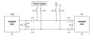
  • I would like to request the calculation of the impedance of the Capacitor and the impedance of the inductor in the picture below.
    Because it is to match the impedance value presented by Datasheet with the value I calculate.

    Does the answer below mean that if I change from THVD8000 to 8010, can I get a normal output without outputting the wrong bit value?

    ------------------------------------------------------------------------------------------------------------------------------------------------------------------------------------------------------------------

    That was calculated at a 300KHz modulation frequency - not 500KHz - as I mentioned in the last thread you really shouldn't be running the system at 500KHz - the bus is too long and you are most likely seeing issues due to that + adding additional filtering components should help clamp down on the problem - I still think the THVD8010 might be a better option overall as if you were to switch the noise signal causing false bits wouldn't be high enough to cause false bits + the length of the cable + modulation frequency you are currently using is most likely adding more negatives to your system than the alternatives. 

    ------------------------------------------------------------------------------------------------------------------------------------------------------------------------------------------------------------------

  • Additionally,
    1. Is THVD8000 likely to cause problems due to noise at a frequency lower than the carrier frequency?

    2. I think the carrier frequency is 500 kHz and the inductor value is insufficient. Is it not helpful to design the inductor value satisfactorily by increasing the frequency to 750 kHz?

  • Hojun,

    The full equations are as follows as I have included in your original thread with the design calculator:

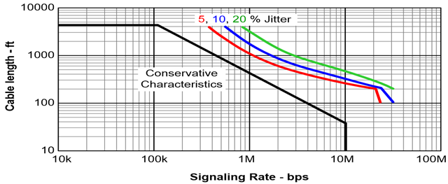
    You'd use a terminated system - so the first, third,  and 4th equations would be the most important + the characteristic distance graph - one note to mention - as included in the last thread you opened - bps rate on the x-axis needs to be divided by 2 - then you can use the modulation frequency to approximate max distance. So a modulation frequency of 500KHz will be equivalent to the 1Mbps x-axis value on the following chart when using the THVD8000/THVD8010 - however this graph assumes 22AWG 120 Ohm twisted pair wire with no impedance mismatch - so real systems may perform slightly worse. 

    Nodes Modulation Frequency Minimum Inductor Value Minimum Capacitance Value Appx. Max Conservative Distance 5% Jitter 10% Jitter  20% Jitter
    2 300KHz 401uH 106.1nF (0.1061uF) 700 ft / 213m 1250ft / 381m Not Listed Not Listed
    2 500KHz 240.6uH 63.7nF (0.0637uF)  400 ft / 122m  1000ft / 304m 1100ft/ 335m 1200 ft/ 361m
    2 750KHz 160.4uH 42.4nF (0.0424uF) 300 ft / 91m 750ft / 229m 1000ft / 304m 1100ft / 335m

    At 300KHz your minimum inductance is 401uH and minimum capacitance is 106.1nF - your setup is not a recommended one at 300KHz

    At 500KHz your minimum inductance is 240.6uH and the minimum capacitance is 63.7nF - your setup violates the inductor but not the capacitance requirement  at 500KHz- however the closer the capacitor to the minimum the better attenuation you will get from lower frequency signals.  

    At 700KHz - the loading isn't as bad as 500KHz but you still violate the inductance requirement. 

    So in both situations the inductor needs to change.

    For your additional questions:

    1. Low frequency noise generation  hasn't been known to be a major issue as the balanced differential setup of the output driver is EMC friendly. Also The carrier frequency does have a +/-25% plus a spread spectrum clock of 30KHz - so signal generation from the device shouldn't be lower than:

    appx. 0.75*Fmod - 30KHz

    That being said - low frequency noise may be coupled in from other sources - so a cleaner VCC (without much ripple) would be advisable and try to have as much distance  as possible in your from low AC frequency higher power lines, also the addition of common mode noise filters (such as common mode chokes) can help with noise coupled onto the bus. 

    2.  No 750KHz will most  not work in your design at 300m and with current loading - the problems that you are seeing are at least in part due to the very long bus relative to your modulation frequency. 

    You are going to have some SI issues in your system due to the bus length and required data-rate -at this point its important to try to minimize that - and the previous suggested solutions in this thread and previous are still my suggestion.

    Best,

    Parker Dodson