This thread has been locked.

If you have a related question, please click the "Ask a related question" button in the top right corner. The newly created question will be automatically linked to this question.

TCAN1043A-Q1: Interface forum

Part Number: TCAN1043A-Q1

Hi TI team:

I found the spec(TCAN1043A-Q1) that TCAN1043ADMTRQ1 supports classic CAN and CAN FD up to 8 Mbps,but when I tested CANFD thouughput,the result did not meet expectations.

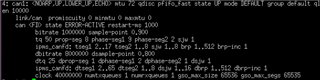
According to the answers to other related questions, I know it has something to do with the CAN controller, and I want to know how you test the throughput with software.

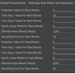
I would also like to know if there are any settings that need to be set? Because I found that setting 1(BRS ON) and 0(BRS OFF) for CANFD flags will affect the result.

BR,

Juno Chen

  • Juno,

    Thanks for bringing this to E2E.

    8Mbps can be achieved by the transceiver, but the signal integrity at that high of a data rate significantly depends on the physical topology of the CAN bus. This means the full length of the CAN bus, all other components, amount of nodes, and length of stubs at each node. What exactly do you mean by throughput though? All the TCAN1043A-Q1 transceiver is doing is translating the signals, so if the throughput is being affected by the transceiver misinterpreting the bits, then there may be some things we can do, otherwise it will be dependent on controller configuration which we cannot directly support, but can help out.

    BRS is the bit-rate switching that happens from the arbitration and data phase, so if this is turned off the CAN frame will not being configured correctly and throw errors.

    Regards,

    Eric Hackett 

  • Hi Eric,

    Thanks for reply.

    We will check again our controller configuration.

    What exactly do you mean by throughput though?

    =>We use while loop to test how many bits/sec can be received by other node
    P.S. We only calculate the data field

    BR,

    Juno Chen

  • Hi Eric,

    Please help check if there is any error in the settings.

    MCU configuration:

    SoC configuration:

    BR,

    Juno Chen

  • Hi Juno,

    This configuration looks correct. You can see a bit more information on CAN controller configurations in the user's guide linked below.
    https://www.ti.com/lit/ug/sllu270/sllu270.pdf?ts=1688584803718&ref_url=https%253A%252F%252Fwww.google.com%252F 

    CAN FD frames are separated into different segments. The first segment is for arbitration and control bits and is transmitted at the nominal data rate (1Mbps in your setup) This segment contains the 11- or 29-bit frame ID, and control bits which help determine if the frame is a HS CAN frame or a FD CAN frame. If the FDF bit is set (controlled by the BRS configuration in the CAN controller), then the data segment of the CAN frame will be transmitted at the data rate determined by the Data Bitrate configuration. The CRC field is also sent during this faster segment. 

    Because The CAN frame is made up of different parts that are transmitted at different speeds, the average rate of data or throughput will be less than the maximum configured data rate. In order to increase throughput, make sure you are sending larger payloads (up to 64 bytes). This will decrease the header-to-data ratio so more of the available bandwidth is spent on meaningful data. 

    Let me know if you have any more questions. 

    Regards,
    Eric Schott