This thread has been locked.

If you have a related question, please click the "Ask a related question" button in the top right corner. The newly created question will be automatically linked to this question.

DP83869HM: 100M Media Converter no traffic on or above Layer 2 Ethernet

Part Number: DP83869HM
Other Parts Discussed in Thread: DP83869

DP83869HM: 100M Media Converter no traffic on or above Layer 2 Ethernet


Dear Sir,

We are using DP83869HM as a 100M media converter with the following topology:

 PC_A <--- copper --> DP83869 board #1 <---> transmission medium eg. fiber <---> DP83869 board #2 <-- copper --> PC_B

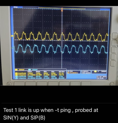
We have successful auto negotiation and stable link up. All registers show base page/code word sent and received with no problem.

Based on the above topology, we have successful layer 1 Ethernet communication.

However, any traffic type between the two PC's belonging to layer 2 Ethernet (and above) will not pass.

PC_A and PC_B happen to be on the same subnet, ARP requests are sent by each PC with no response. Ping test returns "destination host unreachable" meaning there is no route to destination to begin with.

To rule out any PC setup issue, when connecting PC A and B directly, ARP requests are answered by each machine and ping test is successful. This means the problem is not within PC_A or PC_B but with the DP board.

We have even tried to increase the inter packet gap of each NIC on each PC, as well as turning off Energy Efficient Ethernet. Again, link was up and stable; but still, there was no traffic on layer 2 Ethernet and above.

We tried everything with no luck.

We then decided to have a deeper look into certain registers, hoping to find something unusual to use it as a lead. Most registers readings looked normal, except:

  1. Register 13h (bit [2]) showing a flag for Overflow/Underflow. The datasheet stated that this error explained in CDDS document #475 which we cannot find. The datasheet also stated that in this case of error it is recommended not to turn on DS, we have no idea what DS stands for.
  2. We have also noticed that register 4F shows no sync, but we believe that this register may not be of concern for 100M media converter mode.
  • Register 10h bit [11] value is 1 instead of 0.


We are not sure but we think the problem is within the Tx or Rx FIFO's size of the copper side but don’t know what to do.

We seek your assistance..

Below are stable readings of selected registers for your kind review:

0x0

3100

0x1

796D

0x2

2000

0x3

A0F1

0x4

0181

0x5

CDE1

0x6

006D

0x7

2001

0x8

4006

0x9

0000

0xA

0800

0xD

401F

0xE

0000

0xF

F000

0X10

5848

0X11

First 7F02 Next 6F02

0X12

0000

0X13

First 1C44 NEXT 0004

0X14

29C7

0X15

0000

0X16

0000

0X17

0040

0X18

6150

0X19

4004

0X1A

0002

0X1E

0012

0X1F

0000

0XC00

2100

0XC01

614D

0XC02

2000

0XC03

A0F1

0XC04

0020

0XC05

0000

0XC06

0000

0XC07

2001

0XC08

0000

0X6E

0A0C

0x1DF

0045

0x01EC

1FFD

0x4F

0200

0x2D

0000

0xC10

3148

0x0032

0050

0x006F

0000

0x0C19

First  0010 next 0000

0x0C18

01FF

0x002E

0221

Looking forward to your kind assistance,

Regards,

Sandeep

  • Hi Sandeep,

    Are you using our EVM or your own custom board?

    What SFP modules are you using? 100 mbps or 1gps for fiber connection?

    Instead of connecting two 869s, can you replace one of them with a switch to see if the issue continues?

    Regards,

    Alvaro

  • Dear Alvaro,


    Yes we are using our own boards not EVM. 

    There are no SPF’s, we are using the LVDS signal between SOP/SIP and SIN/SON with non-fiber medium (eg. Coax or twisted pair). 

    The SD is tied up to ground otherwise DP chip will not function properly. 

    Transmission medium is fine and auto negotiation took place successfully and periodic fast link pulses are exchanged properly. 

    It is not possible to try the system with one leg.   Do you have another suggestion please?

    From the long time we spent with the DP chip, the problem is likely to be within the Tx/Rx buffers of RJ45 side. 

    The only difference between layer 1 traffic and above layers (with respect to media converter) is the size of data chunks transmitted. 

    In layer 1, auto negotiation and periodical FLP’s are short and have bigger gaps. 

    In layer 2 and above, data size is larger and definitely the gap is narrower. 


    Any other method you would like us to try Alvaro?

    Also. Have you noticed anything unusual with register data provided?

    Is CDDS #475 related to media converter mode?


    Regards 

    Sandeep 

  • Hi Sandeep,

    Pin 24 SD is active low, this may be the reason you're seeing link up without being able to send data.

    As another basic check, Auto-neg will happen on the copper side, but not on the fiber side. Because of this we need to be sure that the speed on the copper side is the same as the fixed speed on the fiber side (100 Mbps). I checked your Registers and it seems like it is indeed set at 100 Mbps, but it wouldn't hurt to double check.

    Running the PHY in different Loopback modes can help determine where the problem lies. Table 9-1 in Section 9.3.4 Loopback Mode in the Datasheet shows which loopbacks work in Media Converter mode.

    The CDDS #475 comment you found in Register 13 is a massive typo on our part. Please disregard it. 

    Please let me know if this helps.

    Regards,

    Alvaro

  • Dear Alvaro,


    Thank you for your response,
    We have checked PC_A and PC_B: both show link up at 100mbps full duplex. But at the same time both PC's show no connectivity on IPv4 level (which is the main problem).


    Below are a number of questions, I would very much appreciate your input.


    1- Are the values of registers 4h=0181 and 5h=CDE1 okay for 100M media converter mode?


    2- Register Ah shows local and remote receivers not ok. Is this fine for 100M media converter mode?


    3- Register 13h bit #2: is it okay for this bit to be "1" in 100M media converter mode?


    4- Register 4Fh shows 0200: is this okay for 100M media converter mode?


    5- Regarding loopback suggestion, I forgot to mention that we have used a scope to probe SOP/SON output as well as SIP/SIN input. Although it's hard to capture real data in real time using standard scope, the scope shows a 8ns (125MHz) square wave of repeating 01.. from SOP/SON output. We see a clean (after conditioning) received signal of the same sent repeating 01 entering SIP/SIN at around 600mV. The repeating pattern starts only when the end to end system is connected (as described in the original post above). The question is: what is this sequence and what does it tell us. Please elaborate.


    6- Sometime ago during testing, we set the system to media converter 100M forced mode, at that time link was not stable due to previous faults from our side, however, during the times the link was up back then, we attempted many pings, of which one or two were successful and we got a response back and this never happened again. What is interesting is that during the couple of times we got the ping response it showed a huge round trip delay. We don’t know why. Can you conclude anything from the info in point 6 herein ?


    Your guidance and answers to the above 6 questions will definitely help us narrow down where to look next.


    Awaiting your kind response,
    Regards,
    Sandeep

  • Hi Sandeep,

    1-4 are fine, please try loopback modes to isolate issue. 

    For Point 6, if you can recreate good ping, could you send data using a packet generator (in the pc) to send traffic from PC1 to PC2?

    Regards,

    Alvaro 

  • Dear Alvaro,


    Apologies for the delay. 

    One quick question, register 18h reads 6150. This means LED2 source is Tx/Rx activity (in harmony with table  9-10 of datasheet for copper to 100baseFX). 

    However, according to register 18h, LED1 is sourced from 1000BT which contradicts with table 9-10. 


    1- is this okay for 100M media converter mode?


    2- we see LED2 being constant ON which is as expected, but LED1 blinks randomly. The question is who is giving us the right info about LED1 source?: table 9-10 or register 18h value ?


    3- in 100M media converter mode: if you find a problem in Digital  Loopback (ie near or within the signal processing section) what does that tell us?


    Thanking you,

    Sandeep 

  • Hi Sandeep,

    I was wondering where you went! 

    Table 9-10 tells you the state based off the Strapping. It sounds to me like you are in RGMII to 100Base-FX, which is OPMode 010,

    which states:

    • LED_0 set to Linkup
    • LED_1 & LED_2 to RX_Activity  

    These functionality can always be programmed differently.

    As to who do you trust, I would trust whatever Register 18h is telling you.

    Also, I don't think I ever asked you this, but have you tried running the configuration script for Media Conversion?

    I believe the one you need is 9.4.8.3 RGMII-to-100Base-FX Mode

    Please let me know if this helps.

    Regards,

    Alvaro

  • Happy to hear from you again,


    Register configuration for 100M media converter is done as per datasheet (including initializing register 18h=000E). 


    However, during operation register 18h jumps to 6150. 


    All OpMode, ANEGSEL, and other straps are done as per datasheet, as:


    OpMode 2: 1

    OpMode 1: floating 

    OpMode 0: 1


    ANEGSEL DIS: floating 

    ANEGSEL 0: 1

    ANEGSEL 1: 1


    Mirror mode: 0 (pulled down)

    Link loss pass through: 1


    All related registers are ok indicating 100M media converter full duplex. 


    Network adapters on PC 1 and 2 shows 100M full duplex. 


    Pc to pc ping (without media converter) works fine. 


    The puzzle is, on both boards of the media converter:


    Register 6Eh = 0A0C 


    While,


    Register 18h = 6150 


    Please help,


    Best wishes,

    Sandeep 

  • Hi Sandeep,

    Your OpMode settings puts you in 100Base-T to 100Base-FX, which is good.

    Your ANEGSEL settings puts you in a Function that is N/A, please check Section 9.5.1.4 in the SNLS614B Datasheet. 

    I believe you should use Forced 100M, full duplex, MDI mode

    ANEGSEL DIS: floating | ANEGSEL 0: 1 | ANEGSEL 1: 1

    This is important, because as mentioned in a previous reply, Auto-Negotiation only happens on the Copper side, not the Fiber side. We want to Disable Auto-Negotiation and Force the Speed to 100M. (Register 6Eh = 0A0C tells me you have Auto-Negotiation Enabled, we need to disable it).

    Please try these register writes I mentioned in my most recent reply (and pasted below).


    Regards,

    Alvaro

  • Hello Alvaro,

    1. we are going as per 9.5.1.8 table 9-15 . We tried as per 9.5.1.4 before and it didn’t work  by the way 9.5.1.4 contradicts with 9.5.1.8 .

    2. we are already doing this ANEGSEL combination as mentioned in previous reply. 

    3.we have already followed the 100M media converter register sequencing . Why do you want to change to RGMII to 100Fx?

     In my opinion, and from the LED’s we are observing and relating to datasheet:

    the fiber link is showing 1G stable ON (LED1) and blinking LED2 is showing Tx/Rx activity .

    According to table 9-10, OpMode combination 101 is what we selected and it shows on most registers  but register 18h value indicates that OpMode combination is 100 .

    It looks as if OpMode 0 pin (in specific) acts as pulled up as most registers show, and acts as being floated when checking register 18h   

    From your experience and previous posts you came across:

    What may cause the fiber link stact as 1G link while the strapping and register settings are indicating 100M fiber  ?

    4. Also Alvaro, we tried forcing both PC’s to 100M full duplex No auto negotiation. 

    Same outcome. LED1 is stable on and LED2 is blinking and register 18h shows 6150 while reg 6E shows 0A0C


    Regards

    Sandeep 

  • Hi Sandeep,

    The LED_1 1G Link up is concerning. Could you share your schematic?

    Also, are you setting the registers and straps for both 869s?

    Is Pin 22 OpMode[0] strapped per this table?

    Regards,

    Alvaro

  • Alvaro,


    Both 869’s were set up as per datasheet. 

    Also, straps -to our knowledge- are as per datasheet. 


    Attached is 869 schematic for your kind review. Please look into it. We want to rule out any layout problem. 


    Kindly be as thorough as you can in your review of the attached schematics. 


    Restating the problem: within either of the two 869 boards, no communication between copper module and FX module beyond the physical layer within a given 869 chip. 


    Regards,

    Sandeep 

    1832.Schematic.pdf

  • Hi Sandeep,

    Schematic checklists typically take a full business week (would be done by Aug 14th at the latest).

    But upon opening the schematic I immediately noticed this:

    1. The Resistor values aren't what we recommend for strapping in Table 9-6 & 9-7
    2. Is JTAG_TDO ( OPMODE[0] ) being pulled high? Both Resistors connected to it are DNP and again, that values aren't correct.

    Regards,

    Alvaro

  • Thanks for your reply Alvaro,


    0- Kindly go ahead with your review process. Ruling out any issue with layout is a big step towards the solution. Awaiting your feedback on Aug 14th. 


    1- R175 R176 R225 do not exist. Instead, R252 (right of page) is used (alongside R248 for OpMode configuration 101). The SD pin is grounded via R842 otherwise link won’t come up (recommended by TI in other older posts). R174 is needed since JTAG CLK needs to be pulled up in case of triple supply used for 869 (as per datasheet ) and the value of R174 is as per datasheet (please let us know if it’s not the case). Finally R173 is optional for test mode clocking in case test modes are used and have no effect on system (Keeping R173 in place or making it DNP doesn’t matter as we experienced). 


    2- OpMode strapping is done via R252 R248 at the right hand side of the schematics page. 


    Regards 

    Sandeep 

  • Hi Sandeep,

    Thank you for the clarification. I will get back to you after completing the schematic review.

    Regards,

    Alvaro

  • Hi Sandeep,

    I've finished reviewing your schematic (looks good) and have also reviewed our conversation. I sent some misleading replies prior. 

    Your OPMODE & ANEGSEL straps are selected correctly. (Previously I was referring you to the wrong table)

    I did some testing in lab and it looks like there's an error with Register 18h. No matter what mode the 869 is in, the value remains 6150. Please ignore this register.

    More important is Register 1DFh, it should end in a '5', which yours does.

    LVDS signal between SOP/SIP and SIN/SON with non-fiber medium (eg. Coax or twisted pair)

    In your setup, 

    PC_A <--Copper--> 869 <--Fiber-->[probe] 869 <--Copper--> PC_B

    Could you probe your board at the receiving end of the fiber cable to see what kind of signal is making it through?

    Regards,

    Alvaro

  • Thanks for your review and patience Alvaro,


    This may become a lengthy thread but hopefully it’ll be useful for many other 869 users in the future. 


    Reference to your latest text, at least most of the hardware part (so far) is out of the way. 


    Below are system probing at SOP/SON and corresponding SIP/SIN on the receiving end. Two cases: when link is up but no ping command (each PC is only trying to ARP request the other PC).  The other case is the same probing but while continuous ping attempts are performed (ping -t). 


    Attached are the images. 

    We still see a continuous 0101.. 8 nano seconds pulses whenever the FX link is connected. 


    Alvaro, for some reason, we think that, inside the 869 of each board, the 100baseTX module and the FX module are working ok in isolation, but they cannot see each other properly because of something we did but don’t know what. 


    Therefore:


    1- within each 869, Is there any “electrical “ situation where the 100baseTX module and the FX module don’t see each other ? I mean a situation where the 100baseTX module is not electrically connected with the FX module? Do both modules share common signal ground internally?


    2- the RJ45 ground (ie chassis) and 869 ground (PHY_GND in schematics) are isolated by R1 and C3 as per schematics and per datasheet. What happens if they are NOT isolated?


    it looks as if the 100baseTX is receiving data properly from PC and is forwarding the received data to either a wrong path or to an isolated load within the 869.


    Regards,

    Sandeep

  • Hi Sandeep,

    I believe those waveforms look good. Could you use a differential probe to measure these signals? Or subtract one waveform from the other.

    In lab I connected a Packet Generator via ethernet cable to our 869 EVM board, which had been setup in 100M Media Convertor Mode, and used a differential probe on the SOP/SIN line to get the attached waveform.

    As for the questions you asked, please allow me another day to consult with my team.

    Regards,

    Alvaro

  • Hi Sandeep,

    Were you able to get the scope shot? 

    I have a few responses and further ideas for debug.

    Within each 869, Is there any “electrical “ situation where the 100baseTX module and the FX module don’t see each other ?

    • No

    Do both modules share common signal ground internally?

    •  Yes 

    the RJ45 ground (ie chassis) and 869 ground (PHY_GND in schematics) are isolated by R1 and C3 as per schematics and per datasheet. What happens if they are NOT isolated?

    • We recommend this for better EMC performance

    For further debug, could you bring the boards closer together and connect each 869 via AC Coupling Caps (0.1 uF) with length matched wires? I.e replace the "Fiber" cable with the capacitors.

    We want to remove doubt from the coaxial cable being used.

    Regards,

    Alvaro

  • Hello Alvaro,


    We don’t have a differential scope ready now. But we did differential probing before and we got a differential signal similar to the one shown in your previous response. 


    We will definitely do the direct SOP SIP SON SIN direct test that you have recommended. But before that, please note that: You latest response helped to concentrate on a situation that we haven’t analyzed before:


    As per 869 datasheet, the RJ45 chip should have two independent ground pins. One ground pin connected to the center tap of the primary coil (facing line) and the other ground pin is connected to the center tap of the secondary coil (facing 869). 

    As per datasheet, the ground facing line should be connected to chassis, while the ground facing 869 should be connecting to the ground used by 869 (GND_PHY in our case). 


    However, we discovered that our 749 RJ45 chip used in our schematics have both ground’s tied up together internally. Making it only possible to select one ground to be used on both sides. And in our case as per schematics, our 749 is connected to GND_CHASSIS on both sides. 

    This unintentionally makes GND_CHASSIS extend its effect into the DP chip such that the internal 100baseTX module is using GND_CHASSIS and the the internal FX module is using GND_PHY. 

    This is not as per the requirement that the 100baseTX and FX modules should have common ground as stated by your latest response. 


    From the above, if you think our current setup of the 749 RJ45 in schematics critically violates TI recommendations and “could” be the problem then kindly let me know because changing the RJ45 chip and it’s pin layout will take us time. 


    We have identified a new RJ45 chip HFJ11-1G41E-L12RL which we think it meets TI recommendations. Please verify it. 


    If your response suggests changing the chip then you can consider this as the end of the thread. 


    Thank you,

    Sandeep 

  • Hi Sandeep,

    The HFJ11-1G41E-L12RL meets our spec. This FAQ helps interpret the specs https://e2e.ti.com/support/interface-group/interface/f/interface-forum/1161575/faq-dp83867e-how-do-i-choose-magnetics-for-my-industrial-phy?tisearch=e2e-sitesearch&keymatch=%252520user%25253A462093

    A more important issue has just occurred to me. Earlier you mentioned that you aren't using any SFP modules, do you have any DC blocking capacitors on the SGMII/SI-SO lines? Normally they're included in the SFP module.

    Your schematic doesn't show where the SGMII signals get connected to, could you share where they lead?

    Regards,

    Alvaro

  • Hi Alvaro,


    Yes we are using caps between SOP SIP SON SIN. 


    We will try the board after installing the alternative RJ45 module.  We shall open a new thread with reference to this thread if the problem persists in the future. 


    In the meantime, thank you very much. You may consider this thread as closed. 


    Regards 

    Sandeep