This thread has been locked.

If you have a related question, please click the "Ask a related question" button in the top right corner. The newly created question will be automatically linked to this question.

[FAQ] What capacitance should my ESD diode be?

Other Parts Discussed in Thread: ESD2CANXL24-Q1, ESD2CAN24-Q1, ESD2CANFD24-Q1, ESD122

What should be considered when selecting a diode with parasitic capacitance?

  • For an overview of capacitance recommendations for the majority of interfaces, refer to this E2E post.


    There are two aspects in selecting an ESD diode’s capacitance: the systems overall capacitance budget and the diode's insertion loss. In many applications if the diode’s capacitance is too high, the diode can compromise signal transmission of the system during normal operation.

    Note: Power lines, such as USB’s Vcc line, generally do not have a capacitance requirement as they do not carry a high-speed signal.


    System Capacitance Budget:

    The overall capacitance budget of a particular system must be considered. Even if a data line has a low maximum data rate, other components on the trace will add to the overall capacitance on the line influencing the selection of ESD diode capacitance.

    In the case of the CAN interface, the CAN protection device could technically afford higher speeds based on the ESD insertion loss graph (detailed below). However, the overall CAN bus capacitance—including traces, connectors, and other components—must be considered, especially when capacitance limits are standardized. To provide design flexibility, CAN ESD diodes are suggested to have lower capacitances, typically below the 30pF range.

    TI’s ESD2CAN24-Q1, ESD2CANFD24-Q1, and ESD2CANXL24-Q1 have 3pF, 2.5pF, and 1.7pF respectively to provide exceptionally low capacitances.


    CAN Device

    Speed (Mbps)

    Line Capacitance (pF)

    IEC 61000-4-2 Contact (kV)

    Clamping Voltage (V)

    ESD2CAN24-Q1

    < 1

    3

    30

    35

    ESD2CANFD24-Q1

    < 5

    1.6

    25

    36

    ESD2CANXL24-Q1

    < 20

    1.1

    20

    38


    Insertion Loss:

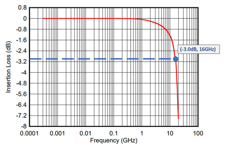
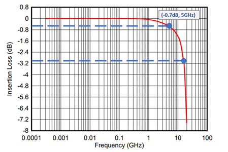
    In the case of high-speed interfaces, one must view the insertion loss graph on the device’s data sheet to verify if the capacitance will comply with the data lines rated frequency. Note that high capacitance devices do not include insertion loss graphs in their data sheets. The frequency of the data line should not exceed the -3dB point of the graph to ensure proper signal transmission. For the ESD122 graph below, the maximum suggested frequency is around 16 GHz.


    If the maximum frequency of the interface is unknown, it can be acceptable to divide the data rate by 2x to achieve a rough estimate of the frequency. For example, take the USB 3.2 Gen2x2 interface that uses ESD122 (0.2pF). The highest rated speeds are 20Gbps across two lanes, meaning 10Gbps per lane at the maximum. With the approximation, the maximum frequency is around 5Ghz per lane which is within the -3dB range of ESD122 below.

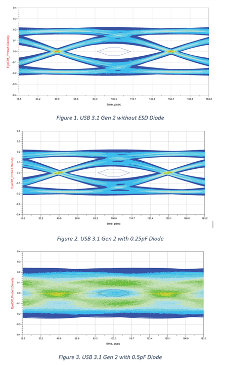
    To further qualify an interface’s ESD diode, the eye diagram test ensures the rise and fall times maintain signal integrity. The degradation of the eye diagram’s rise and fall times is caused by the increase in capacitance. In the first two images below, the test passes while the last image’s rise and fall times are indecipherable, forcing it out of compliance.

    For more information on ESD protection for USB, refer to this application brief.


    Additional Resources