This thread has been locked.

If you have a related question, please click the "Ask a related question" button in the top right corner. The newly created question will be automatically linked to this question.

SN75DP159: Intra-Pair-Skew is too big...

Part Number: SN75DP159

Dear technical TI team,

I'm using the SN75DP159 HDMI2.0 redriver / retimer chip from TI in our product to implement an HDMI2.0 Transmitter interface. The HDMI2.0 interface is properly working so far, but unfortunatly we didn't passed the HDMI compliance test, which we have out-sourced to an external test house.So far all tests passed, except of the the test ID HF1-4. This test will measure the intra-pair-skew on each differential HMDI TMDS signal (1xClock + 3xData). The HDMI specification dictates a maximum intra-pair-skew of 25ps, which is a really small value. The results from our external test house exposed the following intra-pair-skews:

Clock = 38ps
Data 0 = 18ps
Data 1 = 17ps
Data 2 = 14ps

As you can see form those values, the intra-pair skew on the clock signal is too big, and exceeds the 25ps limit by roughly 13ps. Well the data signals does not exceed the limit, but nevertheless they are close to the max. limit of 25ps.

Well we have checked the PCB routing, and we can say that the maximum length difference between Clock+ and Clock- is less than 100um (almost no difference). When we assume a typical signal speed of 70ps/10mm, in a FR4 impedance matched PCB, 38ps would equal to more than 5mm signal length difference. Therefore a length difference of 100um, cannot be the cause for this issue.

Also the HDMI receiptacle does not introduce such a big intra-pair-skew. Further, Allion stated, that they have calibrated the measurement setup, which means that they have compensated any signal runtime differences between Clock+ and Clock-.

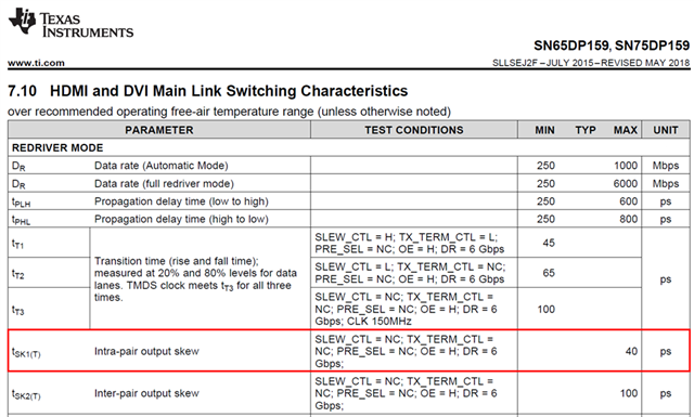
At the moment it looks like the excessive intra-pair-skew is caused by the SN75DP159. The interesting point here is, that the datasheet of the SN75DP159 says, that the maximum intra-pair-skew can be up to 40ps !!!
When I refer to picture below, than the Intra-Pair-Skew is defined as the absolute distance between the middle-line crossing points:
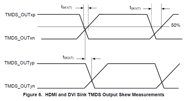
1Tbit equals to 1/6Gbits = 166.666ps. If I’m correct, the max Intra-Pair Skew must not exceed 0.15 * 166.666ps = 25ps.
So if I understand it correctly, the DP159 has a bigger tolerance (40ps), than the HDMI 2.0 specification (25ps) allows, and therewith the DP159 could not meet the requirements of the HDMI2.0 specification.

Can you confirm my thoughts, or am I wrong?

Kind regards

Steffen

  • Hello, Steffen,

    The output inter-pair and intra-pair skew are correct in the datasheet.

    Please also refer to this TI HDMI design guideline. 5684.Texas Instruments HDMI Design Guide.pdf

    I would also recommend placing common mode choke on the HDMI output connector that will help passing the intra-pair skew compliance testing.

    If you would like I can take a second look at your schematic and layout as well.

    Thanks,

    Zach

  • Hello Zach, 

    if the values in the data sheet (40ps) are correct, than we will not meet the 25ps requirements for Intra-Pair-Skew as defined in the HDMI2.0 specification.
    This means the SN75DP159 is not HDMI2.0 compliant!

    Can you confirm this?

    Further, I have attached, the schematic, layout layer 1 & 2, as well as the layer-stack information:

    5466.Schematic_&_Layout.zip.zip

    Below, I have listed also the length of the relevant TMDS signals (signals between SN75DP159 and HDMI receptacle, which you can also see in the PCB's Top Layer = Layer1):

    HDMI4_OUT_CLK+ 14,383mm
    HDMI4_OUT_CLK- 14,313mm
    HDMI4_OUT_D0+ 14,383mm
    HDMI4_OUT_D0- 14,389mm
    HDMI4_OUT_D1+ 13,975mm
    HDMI4_OUT_D1- 13,969mm
    HDMI4_OUT_D2+ 13,981mm
    HDMI4_OUT_D2- 13,969mm

    The maximum length difference can be found between HDMI4_OUT_CLK+ and HDMI4_OUT_CLK- and is just 70um.

    I can tell you that there is another length difference, caused by the HDMI receptacle, which is roughly 800um. 

    But even when you add all the length difference, you will not get more than 870um as worst case scenario. This cannot be the cause for an Intra-Pair-Skew of 38ps, when we assume a signal runtime of ~70ps / 10mm in a typical FR4 PCB with impedance matched traces......

    By the way, In the schematic you will see one HDMI Tx output interface (OUT4). There is another HDMI Tx Interface in the design, named OUT5, which is an exact copy regarding schematic and PCB layout.  Both HDMI Tx interfaces OUT4 and OUT5, show exactly the same Intra-Pair-Skew, as listed below.

    Clock = 38ps
    Data 0 = 18ps
    Data 1 = 17ps
    Data 2 = 14ps

    Best regards

    Steffen

    5466.Schematic_&_Layout.zip.zip

  • Hello, Steffen, 

    Please refrain from discussing secure documentation on E2E public forums. I have removed comments regarding secure information.

    You need to account for the units of Gbps in your calculation above. 1/6Gpbs = 1.33333333 × 10⁻⁹ s / byte.

    I am looking at your schematic and layout. Please allow for 2 -3 business days for me to review and get back to you. 

    Thanks,

    Zach


  • Hello, Steffan,

    Please see my review of your schematic here: 

    DP159RGZ schematic TI_review.pdf

    Thanks,

    Zach

  • Hello Zach,
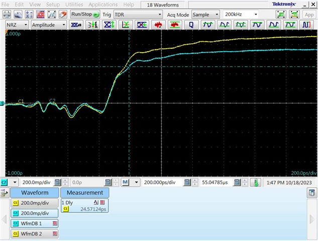
    an external test house did a TDR measurement on the TMDS clock signal. They have probably connected their HDMI to SMA test adapter (which they use for the HDMI compliance test measurments), to our HDMI output, and measured backwards with a TDR device the impulse response. The signal response for the positive and negative signal looks very identical. There is no significant signal runtime difference measureable. I assume that the ripple during the first 400ps, is coming from the SMA and HDMI connector...


    Our external test house, which has executed the HDMI compliance tests, stated that they have calibrated the measurment setup for the Intra-Pair-Skew measurement, in order to compensate signal runtime differences for the single ended probes...

    In the end this means that the Intra-Pair-Skew is caused by the SN75DP159. There is no other source for Intra-Pair-Skew...

    The only way which might help is to use the common mode choke. We have done some simple simulation with the common mode chokes, and it looks like the common mode choke will have a positive effect on the Intra-Pair-Skew, but on the other hand the eye-diagram becmoes a bit closer...

    Regards
    Steffen

  • Hello, Steffen,

    Could you share with me the compliance report?

    Thanks,

    Zach

  • Hello Zach,

    I have sent you a private message...

    Kind regards

    Steffen

  • Hello, Steffan,

    Thank you. I will look at it.

    Regards,

    Zach

  • Hello, Steffan,

    Please place the common mode choke on the clock lane as suggested in the schematic review above.

    Thanks,

    Zach