This thread has been locked.

If you have a related question, please click the "Ask a related question" button in the top right corner. The newly created question will be automatically linked to this question.

TCAN4550-Q1: TCAN4550-Q1 issue related high temparature

Part Number: TCAN4550-Q1
Other Parts Discussed in Thread: TCAN4550, RM46L852,

Dear Team,

We've got an issue related to high temperature. The situation of the failure and the TCAN4550 settings are as follows:

[Issue]

Multiple errors occurred at high temperatures (about 60 degrees), resulting in a reported CAN communication failure. The failure rate is approximately 5%.

Upon checking the Interrupt register (h1050), bits 23, 24, and 25 are set.

Upon checking the Protocol status register (h1044), bits 5, 6, and 7 (Error Warning, Error Passive, Bus Off) are found to be triggered.

[The circuit structure and TCAN4550 settings are as follows]

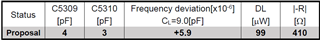
TCAN4550 Bit timing setting : (@40MHz crystal +-10ppm tolerance / Fixed 500kbps )   

BRP = 10 - 1; /    SJW = 1 - 1    TSEG1 = 6 - 1    TSEG2 = 1 - 1;

and we've checked the load capacitor value according to the crystal evaluation report with our PCB board.

[Questions]

        1. Even when I changed the setting from 10TQ to 80TQ for testing, the defect phenomenon remained the same. Do I need to align the bit setting timing of RM46L852 as well?

    1. brp = 1- 1; / sjw = 10 - 1;/ tseg1 = 69 - 1;/ tseg2 = 10 - 1;

    2. As you can see in the block diagram above, the connection between the two boards is not a long CAN cable but a trace of approximately 250mm. If you have any recommended settings for a bit rate of 500kbps at a low speed, please suggest them.

    3. If there are any other improvement suggestions besides changing the bit time, please let me know.

    • Hi Kiman,

      This is not an issue with the bit timing configuration but is almost certainly an issue with the crystal circuit needing some adjustment.  The TCAN4550-Q1 supports both a crystal and a single-ended clock option which can be enabled by "grounding" the OSC2 pin.  At power up the device sources a weak 1uA current out the OSC2 pin and uses a comparator to check whether the voltage on the pin is above or below a 100mV (typ) threshold.  If the pin is grounded, the voltage will be below the threshold, and if it is connected to a crystal, the voltage will be above the threshold.

      If the pin detects a high voltage, then it sources current out of the OSC1 pin to the get the crystal oscillation started.  If the pin detects a low voltage, it disables the amplifier sourcing the current out of the OSC1 pin and instead expects a single-ended clock signal to be input on OSC1.

      There is not a mechanism to disable this comparator after startup so if the voltage on the OSC2 pin drops low enough to trigger this comparator, the device can switch to single-ended mode.  The device has an Automatic Gain Control (AGC) circuit to control the amount of current that is being sourced to maintain an oscillation waveform of approximately 1Vpp with a common mode voltage between 600mV and 700mV.

      If the external load between the OSC1 and OSC2 pins is such that the oscillation waveform is greater than 1Vpp when the AGC is at the minimum output current limit, then the TCAN4550 can't adjust the current any more and the lowest peak voltage of the waveform can drop below the single-ended detection comparator threshold and cause a mode switch.

      This is the result of a high drive level  DL = Irms^2 * Rload which is essentially the power dissipation across the crystal.  A higher power dissipation results in a larger vibration and a larger oscillation waveform.  Therefore, we need to reduce the drive level by either reducing the current or the restive load.

      The first option is to use a series "dampening" resistor (Rd) between the OSC1 and the crystal to restrict the current reaching the crystal and "dampen" the oscillation waveform. 

      The second option is to adjust the Rload by increasing the load capacitance.  As you can see from the following equations, Cload is in the denominator of the Rload equation so an increase in Cload results in a smaller Rload.

      The temperature related failure is also due to a change in the Cload, but typically a reduction in Cload.  You can see that the PCB parasitic capacitance and the parasitic pin capacitance of the TCAN4550's OSC1 and OSC2 pins (designated by Cin and Cout in the equation) make up a large portion of the overall Cload.  These parasitic capacitance sources are not made up of temperature stable dielectric material like the actual load caps (CL1 and CL2).  At higher temperature, this capacitance tends to reduce which in turn increases the Rload and also the DL which will create a larger oscillation waveform amplitude.

      Your crystal evaluation report is a good resource for optimizing the circuit from the perspective of the crystal, but unfortunately the TCAN4550 has this special single-ended mode detection comparator that needs to be considered.  Adding a series dampening resistor between OSC1 and the crystal with a typical value between 30-50 ohms should stabilize the circuit without requiring a change to the load capacitance. If a series resistor is not available, I would suggest you increase the capacitor values (perhaps to around 8pF each) and test again.  The extra capacitance will result in a small frequency shift, but it should still be within the allowed tolerance range defined in the CAN standard.

      See the TCAN455x Clock Optimization and Design Guidelines application note for more information (Link).

      Regards,

      Jonathan

    • Thank you very much for your response.

      Unfortunately, it is currently not possible to insert a resistor for modification. Additionally, increasing the load capacitor may exceed the DL specification of the crystal, which could also be problematic. (Please refer to the crystal specifications and test report below.)
      I remember You mentioned that increasing the load capacitor value would decrease the DL, but according to actual measurements, it actually increases. What are your thoughts on this thing?

      Currently, there is a sufficient margin in the minimum voltage values for VPP at OSC2, as shown in the diagram below. Therefore, I don't think there would be any malfunctioning of AGC exceeding the threshold at high temperatures.

      However, I have some additional questions, so please provide your answers:

      • Is increasing the load capacitor the best option at this point, even if the DL value exceeds the specification?
      • Is it really not worth trying to change the CAN BIT timing value?

    • Hi Kiman,

      It's generally recommended that the bit timing parameters be the same for all nodes on the bus so that all nodes have the same sample point.  It is especially important for CAN FD with bit rate switching enabled.  This is because the bit rate switch occurs at the sample point in the BRS bit.  If the bit timing is different for some nodes on the bus, they will expect the switch to occur at different times and can throw error flags when they suddenly see the data coming from another node that has already switched.  But because you are asking about 500kbps only, I'm assuming you are not running at CAN FD with BRS enabled, so this is not the issue.

      Setting the settings to mach would be a good test, but at a slow 500kbps fixed rate, and a short bus, I'm not certain the bit timing configuration would result in errors that occur only at high temperatures. 

      Do you see any problems with the CANH and CANL signals?

      The only high temperature related communication errors I have seen are related to the crystal circuit.  Instead of adding capacitance to the crystal, you could also try to shift more of the capacitance to the OSC2 side of the crystal and reduce the amount on the OSC1 side.  We have run simulations to confirm that this raises the voltage levels on the OSC2 side, but doesn't change the overall capacitive load in the circuit.

      Do you have the ability to monitor the GPIO1 pin during your temperature testing with a scope probe?

      Regards,

      Jonathan