This thread has been locked.

If you have a related question, please click the "Ask a related question" button in the top right corner. The newly created question will be automatically linked to this question.

TCAN1044AV-Q1: Tr Tf requirement on TCAN1044AVDRBRQ1

Part Number: TCAN1044AV-Q1

Hi Expert,

My customer is using TCAN1044AV-Q1 in their projects.

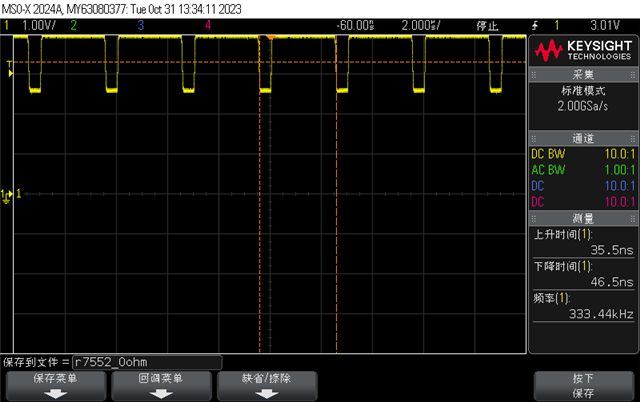
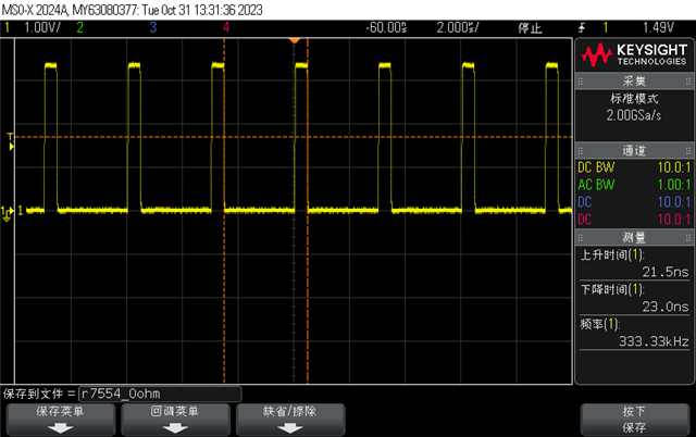
When they test the rise time and fall time of Differential output signal and RXD output signal, the results are different from the datasheet.

However, the test condition is a little different from our test condition.

  • Differential output signal rise time: RL=120Ohm but it is not connected to the CAN bus, and the waveform is shown below.
  • A 10-pF capacitor is placed in parallel with RXD, and the waveform is shown below.
I have 2 questions to consult u.

1. The reason of the test result difference is from different test conditions, right?

2.Would you mind providing me the Tr and Tf of TXD to me?

Thanks a lot!

Kind Regards

Imelda

  • Hi Imelda,

    The scope shots here look a bit too zoomed out to get accurate slew rate readings on these timescales. I would recommend zooming in on the scope to get better resolution on this behavior.

    The rise and fall times of the CAN signal are heavily dependant on the characteristics of the bus, particularly the differential resistive and capacitive loads. Because this test has different load conditions than is shown on the datasheet, I am not surprised to see some deviation from typical values. Given the conditions you describe, the values here look expected to me and don't indicate any issue with the transceiver or network. 

    TXD is a digital input signal that is typically driven by the MCU of the system. Because this signal originates outside of the transceiver, there is no transceiver specification for this parameter. 

    Let me know if you have any more questions. 

    Regards, 
    Eric Schott