This is a question related to a question I asked in the past.
https://e2e.ti.com/support/interface-group/interface/f/interface-forum/1028429/dp83822hf-the-behavior-of-linkup-status-on-basic-mode-status-register-bmsr/3806283
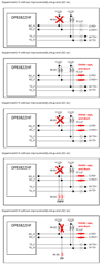
When the SFP module is not inserted and the power is turned on with only the SFP case and connector in the following circuit:
DP83822HF may have a Linkup Status of Valid. (Probability: 70~ 80%)
The Basic Mode Status Register (BMSR) is 0x784D (bit2 = Valid link established).
This causes the Link/Act and Speed LEDs to light or blink.
[Block diagram]
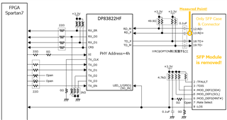
Since the SFP module was not inserted but was linked up, we suspected a change in the input signal of the DP83822HF and measured the waveform before and after the LED's changed.
Measured point:
(1) LED_1/GPIO1 (SD_ IN): No problem (3.3 V fixed)
(2) TD_ P: No problem (sine wave) * However, the measurement point is the 18pin of the SFP connector.
(3) TD_ N: No problem (sine wave) * However, the measurement point is the 19pin of the SFP connector.
(4) RD_P: LED does not light * However, the measurement point is the 13pin of the SFP connector (Measured Point section of the block diagram).
(5) RD_N: No error (0 V fixed) * However, the measurement point is the 12pin of the SFP connector.
From the above, it was found that when an oscilloscope is connected to 13pin of SFP Connector, it does not occur.
Also, clipping the 13pin of the SFP connector with GND did not occur.
Therefore, the LinkUp factor is considered to be the input signal to TD_Ppin.
Further, the waveform measurement of the SFP connector 13pin was continued.
Discharge from 3.3 V to 0 V was confirmed when the oscilloscope was connected.
When the power is turned on while the oscilloscope is connected, discharge occurs immediately after 3.3 V is applied. (Fig.1)
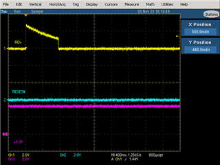
When the oscilloscope is connected after power is turned on, discharge occurs from that moment. (Fig.2)
[Waveform] ch1: RD_P(SFP Connector 13pin), ch2: DP83822HF's Reset, ch3: +3.3V
Fig.1
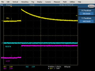
Fig.2
As a guess, the AC coupling capacitor in the RD_P signal line is charged.
From there, the noise is fed into the RD_P pin, and it is considered to be a false detection of LinkUp.
*It is not possible to measure the waveform at the moment of noise because the phenomenon does not occur when the oscilloscope is connected.
In addition, it is not possible to directly measure the RD_P pin of the DP83822HF due to the mounting status of the component.
[Question]
(1) Is this guess correct?
(2) In the first place, are the termination circuits of RD_P/RD_N and TX_P/TD_N correct?
(3) In the first place, what are the conditions under which the Linkup Status becomes Valid in the 100BASE-FX condition for DP83822HF?
If the RD_P/RD_N signal fluctuates, is it valid?
Or is it not just a fluctuation but a valid once the negotiation is completed?
(4) Another possibility was that it was in Loopback mode, but not from register dump results.
Is it possible to detect LinkUp when no cables or SFP modules are connected except in Loopback mode?
(5) Are there any measures that can be taken just by changing register settings without changing the circuit?
[Supplement]
After turning on the power, the register setting of the DP83822HF is changed to the following.
(1) Set address 0x0000 to 0x2100
[bit12]: 0 = Disable auto-negotiation process
(2) Set address 0x000A to 0x4100
[bit14]:1 = 100BASE-FX mode enabled
(3) Set 0x010B to address 0x0011
[bit01]:1 = Enable event based interrupts
[bit00] :1 = INT/PWDN_N is interrupt output
(4) Set 0x0020 to address 0x0012
[bit05]:1 = Enable interrupt on change of link status
(5) Set 0x00A0 to address 0x0017
[bit07]:1 = 50-MHz clock reference, CMOS-level oscillator
[bit05]:1 = Enable RMII mode of operation
(6) Set 0x0100 to address 0x0462
[bit10:8]:001 = LED_3 (Default: Speed, High for 100Base-TX)
(7) Set 0x0001 to address 0x0465
[bit00]:1 = Signal Detect is Active LOW
The register dump when the problem occurs is as follows:
0000: 21 00
0001: 78 4D
0002: 20 00
0003: A2 40
0004: 00 61
0005: 00 00
0006: 00 04
0007: 20 01
0008: 00 00
0009: 00 00
000a: 41 00
000b: 10 00
000c: 00 00
000d: 40 1F
000e: 00 01
000f: 00 00
0010: 0A 85
0011: 01 0B
0012: E2 20
0013: 00 00
0014: 00 FF
0015: 00 00
0016: 01 00
0017: 00 A8
0018: 04 00
0019: 80 04
001a: 00 00
001b: 00 7D
001c: 05 EE
001d: 00 00
001e: 00 02
001f: 00 00
003e: 00 00
003f: B4 FF
0040: C1 1D
0042: 00 00
0101: 20 02
0106: B0 BB
0107: 06 05
010f: 03 00
0111: 60 03
0114: 40 0A
0116: 01 4A
0121: 19 9A
0122: 10 27
0123: 05 1C
0126: 46 1B
0129: 00 0F
0130: 47 50
0155: 00 01
0170: 0E 52
0171: C8 5C
0173: FF 1E
0177: 18 9B
0180: 00 00
0181: 00 00
0182: 00 00
0183: 00 00
0184: 00 00
0185: 00 00
0186: 00 00
0187: 00 00
0188: 00 00
0189: 00 00
018a: 00 00
0215: 01 AF
021d: 06 00
0403: 9F CF
0404: 00 20
040d: 00 08
0410: 20 00
0416: 08 70
0418: 00 00
041f: 00 00
0421: 00 07
0428: 00 00
0450: 0F 41
0456: 00 08
0460: 05 51
0461: 04 10
0462: 01 00
0463: 00 00
0465: 00 01
0467: D7 3F
0468: 00 00
0469: 00 40
04a0: 10 00
04a1: 00 00
04a2: 00 00
04a3: 00 00
04a4: 00 00
04a5: 00 00
04a6: 00 00
04a7: 00 00
04a8: 00 00
04a9: 00 00
04aa: 00 00
04ab: 00 00
04ac: 00 00
04ad: 00 00
04ae: 00 00
04af: 00 00
04b0: 00 00
04b1: 00 00
04b2: 00 00
04b3: 00 00
04b4: 00 00
04b5: 00 00
04b6: 00 00
04b7: 00 00
04b8: 00 00
04b9: 00 00
04ba: 00 00
04bb: 00 00
04bc: 00 00
04bd: 00 00
04be: 00 00
04bf: 00 00
04c0: 00 00
04c1: 00 00
04c2: 00 00
04c3: 00 00
04c4: 00 00
04c5: 00 00
04c6: 00 00
04c7: 00 00
04c8: 00 00
04c9: 00 00
04ca: 00 00
04cb: 00 00
04cc: 00 0C
04d0: 03 02
04d1: 01 8B
04d4: 72 20
04d5: FB C1
04d6: 01 C1
3000: 21 00
3001: 78 4D
3014: 00 FF
3016: 01 00
703c: 00 00
703d: 00 00