This thread has been locked.

If you have a related question, please click the "Ask a related question" button in the top right corner. The newly created question will be automatically linked to this question.

SN65DSI84: Unable to detect SN65DSI84 on i2c

Part Number: SN65DSI84
Other Parts Discussed in Thread: SN65DSI83

Hello Team,

We are using TI SN65DSI84 Bridge chip on our custom board based on Renesas RZV2L processor. We are facing issue in detecting the bridge IC on I2C. Driver probing of SN65DSI8 fails with the below mentioned error.

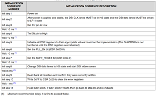
We want to know do we need the initialisation sequence as mentioned in section '7.4.3 Initialization Sequence' of datasheet  for the detection of bridge chip on I2C.  Or is it for proper operation after the detection of bridge chip IC. 

Could you let us know if the provided dtsi entry is proper. Please find attached file for dtsi entry of bridge chip along with panel entry and dsi node.

Also find the below mentioned error logs.

root@sm2s-rzv2l:~# dmesg | grep -i dsi
[    2.012826] sn65dsi83: probe of 2-002d failed with error -22

Below is the output of i2cdetect command , there is no device detected on the address 0x2d. 

root@sm2s-rzv2l:~# 
root@sm2s-rzv2l:~# i2cdetect -y 2
     0  1  2  3  4  5  6  7  8  9  a  b  c  d  e  f
00:          -- -- -- -- -- -- -- -- -- -- -- -- -- 
10: -- -- -- -- -- -- -- -- -- -- -- -- -- -- -- -- 
20: -- -- UU -- -- -- -- -- -- -- -- -- -- -- -- -- 
30: UU -- UU -- -- -- -- -- -- -- -- -- -- -- -- -- 
40: -- -- -- -- -- -- -- -- -- -- -- -- -- -- -- -- 
50: -- -- -- -- -- -- -- -- -- -- -- -- -- -- -- -- 
60: -- -- -- -- -- -- -- -- -- -- -- -- -- -- -- -- 
70: -- -- -- -- -- UU -- --                         
root@sm2s-rzv2l:~# 


Can you help us for resolving the issue.

Thanks,
Nilesh

  • Hello Team, 

    Please find the DTSI entry  we did for bridge chip and LVDS Panel

    &i2c2 {
            #address-cells = <1>;
            #size-cells = <0>;
            pinctrl-names = "default";
            pinctrl-0 = <&i2c2_pins>;
            clock-frequency = <400000>;
            status="okay";
    	dsi_lvds_bridge: sn65dsi84@2d {
                        compatible = "ti,sn65dsi84";
                        reg = <0x2d>;
                        ti,data-lanes = <4>;
                        ti,lvds-format = <0>;
                        ti,lvds-bpp = <24>;
                        ti,width-mm = <217>;
                        ti,height-mm = <136>;
                        ti,lvds-channels = <1>;
                        enable-gpios = <&exp1 10 GPIO_ACTIVE_HIGH>;
                        status = "okay";
                        timings_1024x600_60:display-timings {
                                lvds {
                                        clock-frequency = <65000000>;
                                        hactive = <1280>;
                                        vactive = <800>;
                                        hback-porch = <48>;
                                        hfront-porch = <48>;
                                        vback-porch = <10>;
                                        vfront-porch = <10>;
                                        hsync-len = <64>;
                                        vsync-len = <4>;
                                        hsync-active = <0>;
                                        vsync-active = <0>;
                                        de-active = <1>;
                                        pixelclk-active = <0>;
                                };
                        };
                        ports{
                                #address-cells = <1>;
                                #size-cells = <0>;
                                port@0 {
                                        reg = <0>;
                                        bridge_in: endpoint {
                                                remote-endpoint = <&dsi0_out>;
                                        };
                                };
                                port@2 {
                                        reg = <2>;
                                        bridge_out: endpoint {
                                                remote-endpoint = <&lvds_in>;
                                        };
                                };
                        };
        	};
    };
    
    &dsi0 {
            status = "okay";
            #address-cells = <1>;
            #size-cells = <0>;
    
            ports {
                    #address-cells = <1>;
                    #size-cells = <0>;
    
                    port@1 {
                            dsi0_out: endpoint {
                                    remote-endpoint = <&bridge_in>;
                                    data-lanes = <1 2 3 4>;
                            };
                    };
            };
    };
    
    
    lvds_panel: lvds {
                    compatible = "panel-lvds";
                    label = "AMA-101A01-DU2511-G020";
                    width-mm = <217>;
                    height-mm = <136>;
                    data-mapping = "vesa-24";
                    backlight = <&backlight>;
                    status = "okay";
    
                    panel-timing {
                        clock-frequency = <75000000>;
                        hactive = <1280>;
                        vactive = <800>;
                        hback-porch = <48>;
                        hfront-porch = <48>;
                        vback-porch = <10>;
                        vfront-porch = <10>;
                        hsync-len = <64>;
                        vsync-len = <4>;
                        hsync-active = <0>;
                        vsync-active = <0>;
                        de-active = <1>;
                        pixelclk-active = <0>;
                    };
    
                    ports {
                            port@0 {
                                    lvds_in: endpoint {
                                            remote-endpoint = <&bridge_out>;
                                    };
                            };
                    };
            };


    backlight: pwm-backlight {
                    compatible = "pwm-backlight";
                    pwms = <&mtu3 0 500000>;
                    brightness-levels = <100 99 98 97 96 95 94 93 92 91
                            90 89 88 87 86 85 84 83 82 81
                            80 79 78 77 76 75 74 73 72 71
                            70 69 68 67 66 65 64 63 62 61
                            60 59 58 57 56 55 54 53 52 51
                            50 49 48 47 46 45 44 43 42 41
                            40 39 38 37 36 35 34 33 32 31
                            30 29 28 27 26 25 24 23 22 21
                            20 19 18 17 16 15 14 13 12 11
                            10  9  8  7  6  5  4  3  2  1
                             0>;
                    default-brightness-level = <50>;
                    status = "okay";
            };
    

  • Hey Nilesh,

    You need to follow the initialization sequence shown in section 7.4.2 of the datasheet for proper operation of all functions of the Sn65DSI83.

    After confirming that the initialization is correct. Try using the 0x2D address to see if that works. If it does not read try reading from 0x2C.

    If possible can you confirm if the device can send out an ACK?

  • Hello Vishesh,

    Is this initialization sequence needed for I2C detection of the bridge chip IC. As we are not able to detect this IC.

    In the datasheet it is mentioned that "The SN65DSI84 local I2C interface is enabled when EN is input high" , so this means for normal I2C detection we need only EN pin to be high not full initialization sequence needs to be followed. Please correct us if our understanding is wrong. 

  • Hey Nilesh,

    You are correct that the I2C should be enabled simply based of the EN, but its best to remove all causes of error when debugging. Ensuring the initialization process is correct will make sure that any issue is not stemming from there.

    Also have you tried writing and reading from address 0x2C as a I mentioned?

    Are you able to send the actual register values being written to? it will be mush easier for me to confirm that you are properly setting registers using that. 

  • Hello Vishesh,

    Can you provide reference device tree entry for SN65DSI84 Bridge chip? And also can you let us know if attached DTSI entry provided above is correct or not.

  • Hey Nilesh,

    I cannot verify the DTSI entry without verifying with the panel specs you are using. Regarding the reference tree entry, TI does not use this. We use an aardvark I2C adapter, but given that you cannot read or write to the device I cannot support. Can you confirm you are writing to the correct address based of the ADDR pin on the device?

  • Hi Vishesh,

    We are able to get the bridge chip detected in uboot by only enabling the EN pin. And we checked the signals by probing the i2c line in both kernel and uboot, we get proper address of bridge chip IC in uboot, but in kernel the address is not appropriate.
    And can you provide any reference of DTSI node which you use for in your source.

    Thanks
    Nilesh  

  • Hey Nilesh,

    Here is a reference Linux script that may help. Please have a look at the following thread.

     https://e2e.ti.com/support/interface-group/interface/f/interface-forum/549283/sn65dsi83-sn65dsi84-sn65dsi85---linux-driver/2006135#2006135

    FYI as it says in the thread TI does not support any software for these devices, and any software provided is as is.