This thread has been locked.

If you have a related question, please click the "Ask a related question" button in the top right corner. The newly created question will be automatically linked to this question.

PCA9534A: Multiple I2C IO Expander interface with MCU through Level translator and I2C Extender

Part Number: PCA9534A
Other Parts Discussed in Thread: TXB0102, TCA9539, P82B715, TCA9406, TCA9803, TXS0102, P82B96

Hi Team,

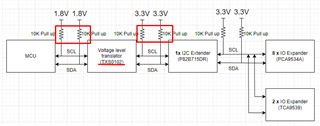
We have implemented the below circuitry in one of our board. 

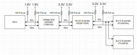
In this application, the MCU is STM32H747 which is 1.8V I2C rail. we have used TXB0102 level translator for converting the I2C bus signal from 1.8V to 3.3V. As there are 10 slaves ( 8 nos of 8 bit I2C IO expander (PCA9534A) and 2 nos of 16 bit I2C IO Expander (TCA9539) ), we have used 1 no of P82B715 I2C extender.

Please check the above implementation. Please let us know if any change/ modification is requred for this appication.

Thanks.

  • The TXB does not work with I²C. Use a translator that supports open-drain signals, e.g., TXS0102/TCA9406 or TCA9803.

    Is the I²C extender really necessary? What is the total trace length? If it does not exceed about 250 cm, you will not exceed the I²C limit of 400 pF, and you can use just a translating I²C buffer (TCA9803) without an externder.

  • Hi Clemens,

    Thanks for your reply. As we have already implemented this circuitry in this design, we can use TXS0102 in place of TXB0102 as both are pin to pin compitable.

    Regarding the I2C length, the total length of I2C in our design is around 50 cm. So, can I use this extender (P82B715) in combination with TXS0102 level shifter? Or extender is not required in this case? If I use extender along with TXS0102, is there will be any issue in case of this application?

  • The P82B715 might be needed if the MCU does not have enough drive strength for the large bus (the TXS is just a passive switch).

    Please note that the TXS already has internal pull-up resistors.

  • Hi Clemens,

    Thanks for the confirmation. We will check the MCU drive strength and let you know.

    So, If we use TXS0102 in our circuit, the resistors marked in Red colour (in below block), are not requied in the circuit. Is my understading correct? If I keep the 10K resistors as it is, will it cause any issue?

  • Additional pull-up resistors speed up rising edges, but also increase the pull-up current and thus the voltage for low signals. This voltage depends on the drive strength of all I²C devices.

  • Hi Aakash,

    As I read through the thread, I have been agreeing with Clemens suggestions. TXB0102 is not meant for buffering I2C signals due to low output low current (I believe it is 20uA, I2C requires 3mA at 0.4V). The selection that you chose here with the TXS0102 is not a true I2C buffer, but will provide level translation purposes, internal pull-up resistors, and rise-time accelerators to help boost the rising edge signal in I2C. Again, TXS0102 does not re-drive / buffer the I2C signal separating the capacitance from side 1 to side 2, but instead provides more pull-up current for the rising edge. 

    The P82B96 acts more like a buffering device, however, it is meant to buffer larger loads up to 4 nF or 4000pF. The limit for fast mode is <400pF. 

    You stated on the output of the P82B96 you have a 50cm cable and 10 x IO expanders. We can estimate with a little math to see how much bus cap is present on the output of the P82B96. 

    3pF / inch of pcb trace is a estimation we use when calculating how much cap will result from length of pcb traces. With wiring, this is a bit different because each cable has its own parasitic bus cap properties, but 3pF / inch is a good est.

    50cm = 19.685 inches, 3pF x 19.685 = ~59 pF in wiring

    Input cap for the 10 IO expanders est. about 10pF per device: 10 x 10 = 100pF

    Total bus cap is estimated to be around 159pF on the output of the P82B96. 

    If I were designing this circuit, I would think the P82B96 is unnecessary due to low bus cap. Implementing the TXS0102 as a level translator would be the only device I would keep since you need translation from 1.8V to 3.3V signals. 200pF is not that heavily loaded of a bus, TXS0102 also has RTA's built into the device (aka one-shots), so this would help with boosting the rising edge from the load of 200pF in combination with the pull-up resistors on the lines. 

    Clemens is also right about the pull-up resistors.

    The ones highlighted in red above in your schematic could be removed since there are internal 10k pull-ups present in the TXS0102. 

    Please let me know if this helps,

    Regards,

    Tyler

  • Hi Clemens and Tyler,

    Thanks for your valuable suggestion.

    We are currently testing the in our lab. When complete circuit is connected, the I2C communication is not able to established.

    During debugging we have noticed that the level shifter (TXS0102) is not able to pass the MCU clock signal (1.8V level) to the 3.3V side when any load (either I2C extender or directly the IO expander) is connected. In this condition, we are able to see the proper clock signal at the 1.8V side, but at 3.3V side some random signal (signal might be distorted) is coming instead of the clock signal. We have checked the same with and without I2C pull up (as you mentioned TXS0102 has internal pull up). But in both condition the results are same.

    We have also checked the I2C level shifter with different input signal (Sine or Square wave signal) at 1.8V side from Function generator (100Hz to 300KHz), but we are getting same some random signal at the 3.3V side.

    But, When no device is connected to TXS0102 at the 3.3V side (means level shifter is in no load), it is able to the pass the signal (either MCU clock or signal from function generator) from 1.8V to 3.3V as expected.

    Please provide some valuable inputs in this case.

  • Please show the oscilloscope trace.

  • Hi Aakash,

    In addition to the scope traces, do you also have a schematic on hand showing how the TXS0102 is connected? 

    Regards,

    Tyler