This thread has been locked.

If you have a related question, please click the "Ask a related question" button in the top right corner. The newly created question will be automatically linked to this question.

DS560DF410: Is the PRBS generator functionality similar to the DS250DF210? What is the minimum frequency for a lock?

Part Number: DS560DF410
Other Parts Discussed in Thread: DS250DF210, , DS280DF810, DS250DF230

Hello,

I was not able to find an answer to a question that I have neither in the datasheet nor the programming guide.

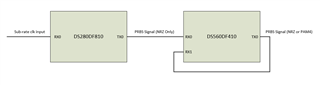
Here is a basic diagram of the circuit in question:

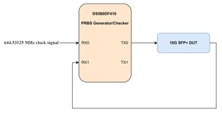
In this thread TI answers that the DS250DF210 can be configured to generate a 10.3125 Gbps PRBS output using a 644.53125 Mhz clock source at its input because the retimer can achieve a lock using input data rates that are divided by 2,4, 8, and 16. 

Is this also the case for the DS560DF410? What are the limits of the retimer locking, are they also 2, 4, 8, and 16?

Kind regards

  • Greetings,

    Please note due to the thanksgiving holidays, response will be provided by Monday afternoon November 27th.

    Regards, Nasser

  • Hi Jan,

    TI's 56G retimers have different adaptation behavior than TI's 10G and 25G retimers.  Because of this, TI's 56G retimers are not expected to acquire/maintain CDR lock to a sub-rate clock input.

    I would not recommend using the DS560DF410 as a PRBS generator if the input signal is a sub-rate clock.  It will work well for PRBS generation if it receives real data at the intended data rate.  For 10.3125 Gbps PRBS generation, I would recommend using one of TI's 10G or 25G retimers.

    Thanks,

    Drew

  • Hi Drew,

    Thank you for the answer. We'd prefer to stay with the 56G version to be able to test 56G PAM4 as well.

    1) If the DS560DF410 is intended to operate at x Gbaud,  Can we use a x÷2 Ghz PLL clock for the CDR lock?

        For example, can we get 10.3125 Gbaud PRBS at TX0 with a lock on to 5.15625 Ghz clock signal input to RX0?

    2) Another related question: The custom PRBS pattern is set to be able to output a pattern of 32 repeating symbols, but the MSBs and the LSBs add up to 8 bytes of data, which can be seen in the image below. Does that mean that it is 32 symbols in PAM4 and 64 symbols in NRZ, or do either the LSBs or MSBs get ignored in NRZ mode? 

    Kind regards,

    Jan

  • Hi Jan,

    Can you share more details on the application for using DS560DF410 as a PRBS generator from a sub-rate clock?  Is this just for evaluation purposes of the DS560DF410, or are you intending to design a basic BERT?

    1) Due to the adaption algorithm on the DS560DF410, adapting to short length periodic signals such as a clock signal can be troublesome, but I may have some ideas depending on your application.

    2) The device supports outputting a pattern of up to 32 repeating symbols for both NRZ and PAM4.  Essentially, each MSB/LSB bit is concatenated to create the output symbol.  For NRZ, MSB[x] and LSB[x] should either both be 1 or 0, to create symbols 11 and 00.  For PAM4, MSB[x] and LSB[x] may be different in order to create the 4 different PAM4 symbols.

    Thanks,

    Drew

  • Hi Drew,

    You are correct, I am intending to design a (handheld) BERT for optical modules and not trying to evaluate the DS560DF410 as a re-timer. I am also interested in using the IC to produce pulse of 24 bits of ones followed by 8 bits of zeroes. 

    1) What ideas do you have? I thought that a PLL clock generator combined with this retimer chip can be used to produce a BERT as per Texas Instrument's own design: https://www.ti.com/tool/TIDA-00426.

    2) The custom pattern generator makes sense now, thank you.

    Kind regards,

    Jan

  • Hi Jan,

    Thanks for providing details on the application.

    Regarding your interest in using the device to produce a pulse of 24 bits of 1s followed by 8 bits of zeros, something to consider is that this is not DC balanced.  The DS560DFx10 devices have integrated AC coupling, so you may run into DC wander if sending repeated non-DC balanced signal.

    1) Note that this reference design implements one of TI's 10G retimers.  TI's 10G and 25G retimers are better suited for generating a PRBS signal from sub-rate clock input than TI's 56G retimer.

    Although more complicated, my thought is the following:

    Use DS280DF810 to generate PRBS data from sub-rate clock input. Send this data to DS560DF410, which can then lock to this signal and generate an NRZ or PAM4 PRBS signal.

    Thanks,

    Drew

  • Hi Drew,

    Thanks for the answer.

    I am aware of the DC wander, I am not planning to send that pattern continuously, but only twice at most.

    I am not sure it makes sense in our application to add another retimer, would a PLL really not work? Regarding the DS560DF410 retimer, you said this:

    Due to the adaption algorithm on the DS560DF410, adapting to short length periodic signals such as a clock signal can be troublesome

    What do you mean by short length? Wouldn't the PLL generate a continous stream of 1010 pattern of bits at 25G which should be ideal for locking onto for the CDR? Or do you specifically need PRBS data for the CDR? 

    Kind regards,

    Jan

  • By the way, would you know if the DS250DF230 can lock to sub-rates and if they're also ÷2, ÷4, ÷8, ÷16 just like the DS250DF210? So at 10G, you can use a ~644 Mhz clock signal for CDR lock and at 25G it would be around ~1.66 Ghz

    Scratch that, I found an earlier reply where you actually tested it working all the way down to ÷64, but with high jitter and recommended ÷(<=32) sub-rates.

    Kind regards,

    Jan

  • Hi Jan,

    What do you mean by short length? Wouldn't the PLL generate a continous stream of 1010 pattern of bits at 25G which should be ideal for locking onto for the CDR? Or do you specifically need PRBS data for the CDR? 

    I mean that a 1010 pattern repeats every 2 bits, while a pattern like PRBS7 is 127 bits.

    In the DS560DFx10 retimers, a key part of acquiring CDR lock is the RX adaptation sequence.  The adaptation algorithm does not behave well with a 1010 pattern and as a result, this can inhibit CDR lock.  The adaptation algorithm is designed for "real" data sequences, or data such as PRBS.

    For TI's own internal testing/evaluation, we have a script we can run in our DS560DFx10 latte GUI that can alter some internal device behavior and allow for lock to a subrate clock pattern for the purpose of PRBS generation.  However, based on my own experience, I have not found this to be a stable configuration, and I would not rely on it for designing a product.  If you'd like to evaluate this on TI's EVM, I can share this with you.  However, this would be shared "as is" and is not something TI can support as a "supported feature" of DS560DFx10 retimers.  CDR lock to clock pattern is not something TI claims to support on DS560DFx10 retimers, and I would not recommend using this configuration sequence in an end product.

    Thanks,

    Drew

  • Hi Drew,

    That is clear now. Thank you for all the answers!

    I will try switching to a DS2xxDFxxx variant and use a sub-rate clock instead. If needed, I will use your idea to feed a 25G PRBS signal into the DS560DF410 for PAM4 capability.  You've solved my issue.

    Enjoy the (upcoming) weekend and kind regards,

    Jan

  • Hi Jan,

    Glad to have helped!  One thing I'd like to note is that if you'd like to support 26.5625 GBd PAM4 through cascading DS2xxDFxxx to DS560DF410, you'd need to select DS280DF810 as this is the only 25G/28G TI Ethernet retimer supporting 26.5625 GBd within its CDR lock range.

    Thanks,

    Drew