This thread has been locked.

If you have a related question, please click the "Ask a related question" button in the top right corner. The newly created question will be automatically linked to this question.

TUSB320: DRD mode - schematic proposal

Part Number: TUSB320
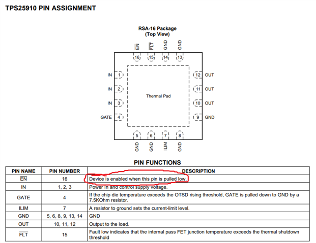
Other Parts Discussed in Thread: TPS25910

Hi,

We use TUSB320 on one of our evaluation board.
We want to use DRD mode (Host/Device) - more or less OTG in USB notation.

The TUSB320 shall convert the USB interface from our MicroProcessor (USB 2.0 with PWR, VBUS, ID, OC, ... pins) to a USB-C connector with CC handshake.

I have studied some schematics (from different sources) and it is not clear for me how to handle following topics:

ID pin and PWR pin:
In some designs I saw that the ID pin is just connected to the input of the MicroController with the USB interface. In other designs I saw that additionally the ID PIN output from TUSB is used to enable the Power switch.
In the designs, where ID pin is just used as input for the MicroController, the MicroControllers output "USB_PWR" is used to control the enable of the Power Switch.
Which solution is prefered / has highest stability?

VBUS:
When our device acts as a host (DFP), VBUS must be delivered by the Power switch. In such a case a capacity of some µF also used to stabilize the energy there.
If we then switch to peripheral (UFP) mode, we should only listen (sense) if VBUS is present. But how to handle the capacitor, which takes some time to discharge. It will tell me that there is VBUS present but there is nothing connected ...
How is this normally handled?

Additional info:
We plan to use NO I2C interface. We just want let pin PORT and ADDR in NC state. Do you see any problems here?

Would be great to get some answer - many thanks!

  • Hi Roland,

    The ID pin is high when the TUSB320 is not connected to anything or connected as a sink. In this state, you would want the VBUS switch disabled. The ID pin goes low when the 320 is connected to a device and acting as the DFP.

    As you noticed, There are multiple ways you can implement this. A simple solution is to connect ID directly to the enable pin on a VBUS switch like the TPS25910. 

    Another way is to have ID be the input to an Microcontroller, and to have the Microcontroller enable the VBUS switch. Either way could work if designed correctly.

    If we then switch to peripheral (UFP) mode, we should only listen (sense) if VBUS is present. But how to handle the capacitor, which takes some time to discharge. It will tell me that there is VBUS present but there is nothing connected ...

    When the device is disconnected, the TUSB320 will set ID high by default. This is the sink state and should disable your VBUS switch, allowing VBUS to drain.

    We plan to use NO I2C interface. We just want let pin PORT and ADDR in NC state. Do you see any problems here?

    You do not need to control the device using I2C for it to work so this is ok. The implementation you're describing would be GPIO mode.

    I hope this helps, let me know if you have any more questions.

    Best,

    Shane

  • Thank you for your quick answer!

    I also found a schematic from your EVAL EVM board. May can answer here two questions:

    1) Red circle: 
    Why is here a Schotky diode placed? My understanding is that this connection should not be necessary. The "IN" of the TPS25910 is supplied by the PWR_IN and the uAB_VBUS should be directly connected to the "OUT" of TPS25910.

    2) Orange circle:
    Also here the question, why there is a Schotky diode placed? What would change (advantage/disadvantage) if it is replaced by a "0" Ohm resistor?

    Many thanks!

  • Hi Roland,

    When you consider this EVM is placed between the upstream facing micro-AB receptacle, and the downstream facing Type-C receptacle, these diodes are ok to have. 

    The diode in red allows VBUS to enter the VBUS switch from the UFP micro-AB receptacle. This would also let the micro-AB VBUS drive PWR_IN, as PWR_IN can be powered from a DC input, the micro-AB VBUS, or the Type-C VBUS depending on the configuration.

    When the 320 is configured as a source (DFP) the VBUS switch connects the input (either from micro-AB or DC_IN) to the output on the Type-C_VBUS.

    When the TUSB320 is connected as a UFP, the VBUS comes from the Type-C receptacle. In this case the VBUS switch is disabled, yet the diode in yellow will allow the Type-C_VBUS to loop around to micro-AB VBUS, then drive PWR_IN.

    If the diode in yellow was replaced with a 0-Ohm resistor, the micro-AB VBUS could entirely pass the VBUS switch with no consideration of UFP/DFP on the CC controller. This may not be desired if you connected a micro-AB cable yet still want a UFP configuration on the CC controller.

    Best,

    Shane