This thread has been locked.

If you have a related question, please click the "Ask a related question" button in the top right corner. The newly created question will be automatically linked to this question.

DS90UB927QEVM: Can not send information from serializer to deserializier

Part Number: DS90UB927QEVM
Other Parts Discussed in Thread: ALP, USB2ANY,

Dear Sir

I would like to know how to access the deserializier(928) and MCU through serializer(927-evm).

hardware connection: signal generator(LVDS+I2C)→ 927-evm→ FPD_LINKⅢ→ deserializier(928) and MCU

Current situation:

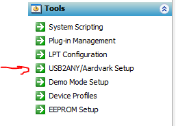
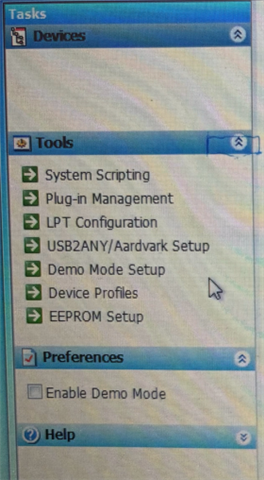
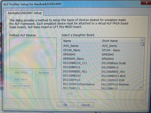
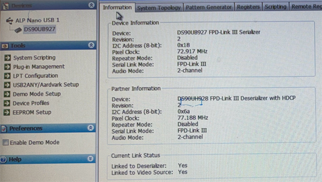
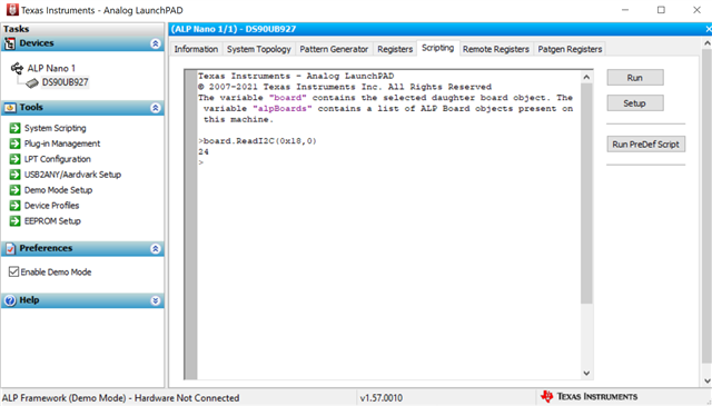
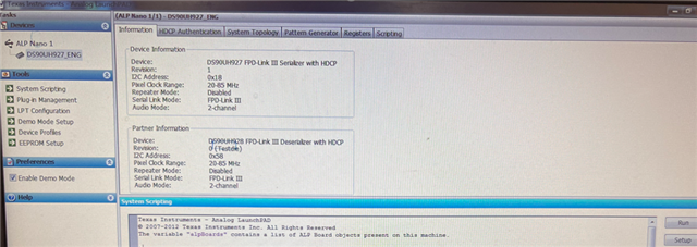
1, ALP connection successful.

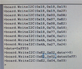
2, 927 setting register: 0x18 write OK

0x18, 0x18, 0x19, 0x2F

0x18, 0x03, 0xDA

0x18, 0x07, 0xE2, 0xE2

0x18, 0x70, 0x58

0x18, 0x77, 0x58

0x18, 0xC6, 0x21

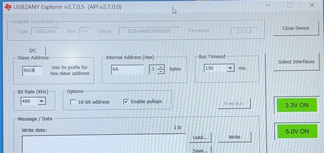
3, 928 setting register: 0x6A write fail

0x6A, 0x26, 0x14, 0x26   NG

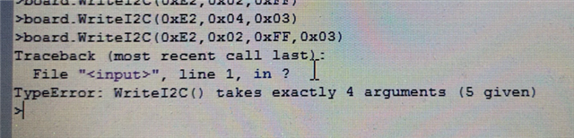
4, MCU setting register: 0xE2 write fail

0xE2, 0x02, 0xFF, 0x03   NG

0xE2, 0x04, 0x03   NG

PS: lock signal is high when power on.

Thank you very much.

Looking forward to your reply

  • Hi Emily,

    Why are you using I2C address 0x6A for the deserializer? The ALP software shows that deserializer's I2C address is 0x58.

    What is the MCU I2C address?

    Can you also disable Demo mode and let me know if you can R/W to the 928 registers?

    Best Regards,

    Gil Abarca

  • Hi Gil

    Thank you for you reply.

    Why are you using I2C address 0x6A for the deserializer? The ALP software shows that deserializer's I2C address is 0x58.

    => Because my hardware design setting is 0x6A in 928. But I don't know why ALP recognized as 0x58 automatically.

    Could I set 928 I2C address as 0x6A using ALP?

    What is the MCU I2C address?

    => MCU I2C address is 0xE2, Also can't be accessed.

    Can you also disable Demo mode and let me know if you can R/W to the 928 registers?

    => I can not R/W to the 928 registers after removing the USB driver.

    I have no experience with 927-evm, Thank you very much for your more help.

  • Hi Emily,

    There are a couple of things that need to be done here:

    1. Update your ALP software. You can download it here.
      1. Download both the framework and the profile update.
     Because my hardware design setting is 0x6A in 928. But I don't know why ALP recognized as 0x58 automatically.
    1. Disbable Demo Mode
      1. Demo mode is a simulation of the devices. Currently you are only doing R/W in simulation instead of the hardware. By default the software will set the simulated deserializer to 0x58. You disable it by unclicking Enable Demo Mode in the preferences section.
      2. You should be using the USB2ANY/Aardvark Setup to select the DS90UB927-Q1

    Can you also disable Demo mode and let me know if you can R/W to the 928 registers?

    => I can not R/W to the 928 registers after removing the USB driver.

    What you need to do is connect the 927 via USB with your computer and the 928 to the 927EVM via the FPD-Link port.

    Once you disable Demo Mode and chose the DS90UB927-Q1 profile you should be able to access the 927,928,and MCU as long as you have I2C passthrough enabled.

    Best Regards,

    Gil Abarca

  • Hi Gil 

    Thank you very much for your reply.

    I'm very sorry to trouble you.

    I have installed the new "Analog LaunchPAD" ,  open ALP→ disable Demo mode → click the "USB2ANY/Aardvark Setup"

    I found that the "USB2ANY/Aardvark Setup" can not add any device.

    Please see below picture: Add key all invalid, can not select.


    Shall I need to connect the "USB2ANY" board to DS90UB927QEVM?

    I don't have the "USB2ANY" board.  Is there any other way to connect it?

    JDIC Emily

  • Hi Gil 

    The ALP have connected successful.

    but the ALP connect to 927-evm with I2C, My signal generator aslo need to connect to 927-evm with I2C.

    my hardware connection: signal generator(LVDS+I2C)→ 927-evm→ FPD_LINKⅢ→ deserializier(928) and MCU

                                              ALP→ USB(I2C)→ 927-evm

    There have 2 Master I2C devices. I can not sent information from my signal generator to 927-evm when connected with ALP.

    Please kindly confirm how to do it. Can I use only ALP to write below information to 928 and MCU? 

    0x18, 0x18, 0x19, 0x2F

    0x18, 0x03, 0xDA

    0x18, 0x07, 0xE2, 0xE2

    0x18, 0x70, 0x58

    0x18, 0x77, 0x58

    0x18, 0xC6, 0x21

    928 setting register: 

    0x6A, 0x26, 0x14, 0x26  

     MCU setting register: 0xE2 

    0xE2, 0x02, 0xFF, 0x03   

    0xE2, 0x04, 0x03  

    Thank you very much.

    JDIC Emily

  • Hello Emily,

    Your SER has the I2C address: 0x18

    The DES has the address: 0x6A

    The way you need to use to write to the SER and DES is as following:

    Local communication:

    board.ReadReg(address, length) ==> Example: board.ReadReg(0x18, 1)
    board.WriteReg(address, value) ==> Example: board.WriteReg(0x18, 0x58)

    Remote communication:

    board.ReadI2C(Device address, Register Address, length) ==> Example: board.ReadI2C(0x6A, 0x00, 1)
    board.WriteI2C(Device address, Register Address, value) ==> Example: board.WriteI2C(0x6A, 0x01, 0x01)

  • Hi Sir

    Thank you for your reply.

    I'm sorry, I don't know how to use ALP.

    How to access 927, 928 and MCU on which operation tab of ALP and how to set it? 

    1, please check below step, Is this correct?

    example: write 0x18, 0x18, 0x19, 0x2F

    in registers tab→  0x18 register →  0-7bit set 0x19→  apply→  reflesh→  0x18 register →  0-7bit set 0x2F→  apply→  reflesh

    example: write 0x6A, 0x26, 0x14, 0x26

    in remote registers tab→  0x26 register →  0-7bit set 0x14→  apply→  reflesh→  0x26 register →  0-7bit set 0x26→  apply→  reflesh

    if the step are OK, how to set 0xE2, 0x02, 0xFF, 0x03 

    2, I want to implement the following settings,  Could you provide the scripting to me? I want to try it.

    927 setting register: 

    I2C speed settings: 0x18, 0x18, 0x19, 0x2F

    Pass through: 0x18, 0x03, 0xDA

    Slave ID(0), Alias(0): 0x18, 0x07, 0xE2, 0xE2

    Slave ID(1): 0x18, 0x70, 0x58

    Alias(1): 0x18, 0x77, 0x58

    INTB: 0x18, 0xC6, 0x21

    928 setting register: 

    I2C speed settings: 0x6A, 0x26, 0x14, 0x26  

     MCU setting register: 0xE2 

    Display Backlight PWM setting 100%: 0xE2, 0x02, 0xFF, 0x03   

    Display Enable : 0xE2, 0x04, 0x03  

    Thank you very much.

  • Hi Emily,

    Gil is out of office so I am handling this thread for now. 

    The DS90UB927 EVM contains an older USB chipset that has a deprecated Windows driver. I do not recommend using the on-board USB connection to the 927 EVM due to the difficulty in getting the driver to work.

    Other users have encountered difficulty using the 927 EVM USB connection as in this thread.

    https://e2e.ti.com/support/interface-group/interface/f/interface-forum/610214/ds90ub927qevm-ds90ub927qevm-driver-doesn-t-work

    My recommendation to connect to the 927 EVM is to use a separate USB2ANY module (link) or connect to the 928 board and program through there using the back channel.

    Best,

    Jack

  • Hi Sir

    Thank you for you kindly support.

    I have some problem about USB2ANY.

    Now the hardware connection as below:

    PC(USB2ANY explorer v2.7.0.5 API V2.7.0.0) → USB2any board (SDA,SCL GND) → 927-evm board (SDA,SCL GND)→ FPD LINK3→ 928 and MCU 

    step: 927-evm power on → 928 and MCU power on → open USB2ANY software → open device→ select interfaces(I2C) → 3.3V ON, 5V ON

    question1: Is the software and hardware connection method correct?

    question2: How to define slave address, internal address and write data?

    question3: How to write registers, what are the format about write and access the registers.

    question4: When I click "load ", what is the format of document. I want to create a new register document.

    My 927-evm address is 0x18, 928 address is 0x6A, MCU address is 0xE2

    example: I want to write 0x18 0x18 0x19, how to set ?

    JDIC Emily.

  • Hi Emily,

    Based off of your previous screenshot with ALP ("The ALP connection successful"), it looks like you can use ALP without using the separate USB2ANY module. The USB2ANY explorer is normally not used for reading and writing I2C commands. ALP is the recommended GUI for interfacing with FPD-Link products.

    Could you try this in the "Scripting" tab in the UB927 profile? If this method works, then we can disregard using the USB2ANY module.

    • Write "Board.ReadI2C(0x18, 0)"

    This will read from register 0 on the UB927 and return the I2C address in decimal form.

    The above screenshot is in demo mode since I do not have a UB927 but should have similar results for you if the USB drivers are working correctly.

    example: I want to write 0x18 0x18 0x19, how to set ?

    In the scripting tab, write "Board.WriteI2C(0x18,0x18,0x19)"

    My 927-evm address is 0x18, 928 address is 0x6A, MCU address is 0xE2

    The 928 I2C address will automatically be recognized by the 927 in register 0x06

    To set I2C pass through and setup communication to MCU:

    Board.WriteI2C(0x18,0x3,0xDA)

    Board.WriteI2C(0x18,0x7,0xE2)

    Board.WriteI2C(0x18,0x8,0xE2)

    Best,

    Jack

  • Hi Jack

    Thank you very much for your help.

    I can write registers using scripting tab.

    But I have one question:

    In 0xE2, 0x02, 0xFF, 0x03  , there have 2 parameters(0xFF,0x03) need to write in 0x02 register.

    I can not run  "Board.WriteI2C(0xE2,0x02,0xFF,0x03)"

    How about the write format of 2 values?

    Thank you very much.

    JDIC Emily


  • Hi Emily,

    The board.WriteI2C() command only writes 1 byte at a time. In order to write 2 bytes to the same register in the MCU you will need to do the following.

    data = 0xFF03 // 16-bit data

    board.WriteI2C(0xE2,0x02, data>>8) // MSB of data

    board.WriteI2C(0xE2,0x02, data & 0xFF) // LSB of data

    Best,

    Jack

  • Hi Jack

    Thank you very much for your reply.

    1, I already run all command, But it seems that this command(0xE2 0x02 0xFF 0x03) does not implement the function.

    0xE2 0x02 0xFF 0x03: MCU PWM output 100%, PWM need high, but now PWM=0

    2, The "board.ReadI2C()" can only read 1 byte, I'd like to read below command, have more than 2byte. 

    0x18, 0xC7, 0x19, 0x00
    0xE2, 0x30, 0xE3, 0x30, 0x01
    0xE2, 0x00, 0xE3, 0x00, 0x07

    Please share the command.

    3,  After I buy the DS90UB927QEVM board back, do I need to burn some files on the DS90UB927QEVM board by case?

    Thank you very much.

  • Hi Emily,

    1, I already run all command, But it seems that this command(0xE2 0x02 0xFF 0x03) does not implement the function.

    In order to write multiple bytes to the same I2C register address use the command

    • board.WriteI2C(0xE2, 0x02, [0xFF, 0x03])

    The data in the brackets will be written to the register in a single I2C transaction.

    2, The "board.ReadI2C()" can only read 1 byte, I'd like to read below command, have more than 2byte. 

    In order to read multiple bytes from the same I2C register address use the command

    • board.ReadI2C(0x18, 0xC7, 0x2)

    The "0x2" at the end indicates the number of bytes to read. Let me know if you need to read register addresses with 16-bit or 32-bit length.

    3,  After I buy the DS90UB927QEVM board back, do I need to burn some files on the DS90UB927QEVM board by case?

    There are no files that need to be loaded onto the EVM.

    Best,

    Jack