Part Number: TCAN4550-Q1
Other Parts Discussed in Thread: TCAN4550
About TCAN 4550-Q1, SPI to can transceiver.
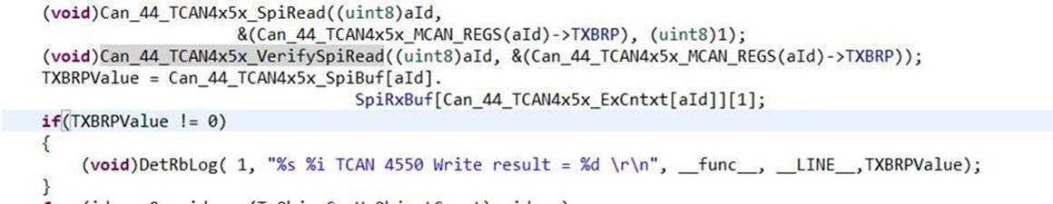
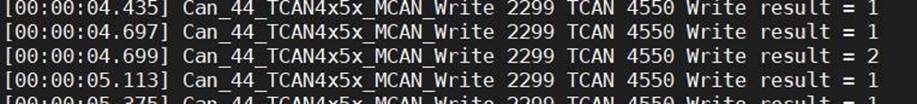
The can transmit status is monitored by reading the "Tx Buffer request Pending" register. According to the chip manual, 0 is defined as "No transmission request pending", 1 is "Transmission request pending", but we have a third state in the project measured 2. Please help confirm: what state is the TCAN 4550-q1 chip in this state? Why is this happening?
Also, what is the minimum write cycle for the TCAN4550-Q1 chip?
If it can not write, what is the register value of TX buffer, Tx Buffer request Pending?
Thanks!