This thread has been locked.

If you have a related question, please click the "Ask a related question" button in the top right corner. The newly created question will be automatically linked to this question.

TCAN1042HV: Bus Fault protection ±70 V condition

Part Number: TCAN1042HV

Hi Ti Experts,

I have the same issue like it is metioned in this post:

https://e2e.ti.com/support/interface-group/interface/f/interface-forum/1300691/tcan1042hv-q1-bus-fault-protection-70-v-condition/4947416?tisearch=e2e-sitesearch

How can I check if I have the H variant or not?

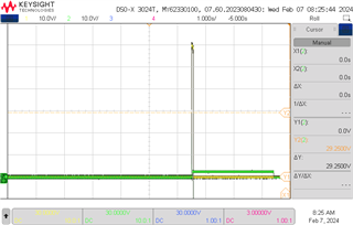
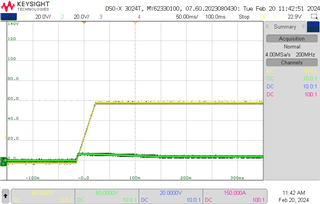
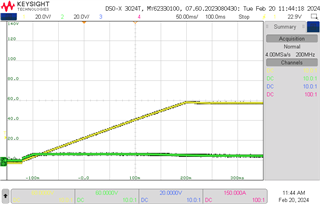
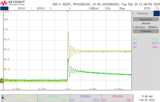
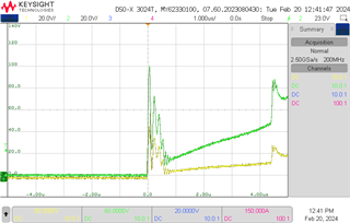
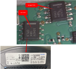
Here is a picture of defect one and a new one. I repeated the test with the same result. The new one is also defect.

Thanks for your help.

Klaus

  • Hi Klaus,

    I can confirm that the units pictured here are 'H' units and are rated for ±70V bus faults. 

    Can you share your test procedure where this unit was damaged?

    Was the power supply active before the connection to the CAN bus made? We have seen in some tests that the transient from connecting an active voltage line to the bus with no series impedance can lead to much higher voltage transients at the device pin that can lead to damage. The recommended test condition is to apply the fault before the voltage source is active so that the bus can be slowly brought up to the fault voltage to avoid these transients. You may also choose to include series impedance on the short to simulate a cable fault which will similarly slow any transient caused by the hardware connection.

    Is the transceiver set up the transmit on the CAN bus during the fault? If the CAN controller continuously drive data instead of going bus off as expected, the transceiver may overheat from the fault current and lead to damage. Make sure that the CAN controller is capable of going into the bus off state when the CAN fault is applied. 

    Regards, 
    Eric Schott 

  • Hi Eric,

    thanks for your answer.

    Where on the component itself can I see whether it is an "H" device?

    I repeated the test a third time with the same test setup. I used a device from a PCB which was assembled about 2 years ago. I assembled it on the same PCB. With this device it worked. Please see following photo:

    I can see that the device marking looks a little bit different.

    In the following plot you can see the voltage on the CAN lines:

    Are theses the same devices?

    Yes the power supply was active before the connection to the CAN bus made.

    The transceiver is assembled on a BMS for battery protection. The BMS is connected to the battery. The BMS is in sleep mode, so the transceiver is not supplied. Then I use a voltage supply which is switch on and connect it in short times to on of the CAN Lines with respect to GND. First it was the CAN Low line. After the first connection the transeiver was defect.

    Please see the Osziplot:

    The yellow line is CAN Low and the green line is CAN H.

    Thanks for helping.

    Klaus

  • Hi Klaus,

    I am able to trace the device by the lot trace code in our system to see the full part number. All of the devices you've shown have the full part number of TCAN1042HVDR. 

    The device does not need to be supplied in order for the +-70V rating to apply. The device should be able to survive this DC condition in any mode as long as it does not overheat from extended operation at the driver current limit. 

    Are you able to repeat this testing with a setup that ensures that the application of the fault is done without a transient component? The usual way to conduct this is to leave the fault voltage supply off until the electrical connection is made. The power supply will then provide a relatively slow ramp up to the fault voltage when it is enabled. 

    Regards,
    Eric Schott 

  • Hi Eric,

    thanks for your answer.

    Ok. Am I also able to track the lot trace code or do I have to ask for it here in future?

    I am going to repeat the test like you have written and come here again.
    Also I will try to plot possible transients.

    Thanks.
    Klaus

  • Hi Klaus,

    Unfortunately lot tracking is only an internal tool. This is important for us to limit access to some information that could be used for counterfeit activity so we are not able to make this information public. You can post here on E2E in the future if you need us to check some information for you but note this should only be used to identify lots that you are unsure of or currently experiencing an issue with. We cannot simply validate lot codes for the same reason we have to keep this information internal. 

    Please keep us updated on the results of your testing. I hope this round goes smoothly.

    Regards, 
    Eric Schott 

  • Hi Eric,

    Thanks for your answer.

    I think you were right.

    I repeated the test with two different power supply. And I used the OutputON Switch of the Power Supplies.

    Here is a plot of the first one:

    chanel1: CAN_H with releation to GND
    channel2: CAN_L

    And here the other one:

    chanel1: CAN_H with releation to GND
    channel2: CAN_L

    The second one has a slower ramp. But it worked with both power supplies.

    If I first switch on the power supply an than connect it to CAN_H ist looks like this:

    chanel1: CAN_H with releation to GND
    channel2: CAN_L

    I madea second try on CAN_L and the TCAN was defective:

    chanel1: CAN_H with releation to GND
    channel2: CAN_L

    You can see voltage transients with 100V. I think that is the reason for the defect.