Goodmorning.
My name's Mauro
I'm calibrating th SN65DSI85 for an IBase IBR210.
I need to know the exact image of test pattern, to test the setup register.
There is an image of test pattern?
Best regards,
MZ
This thread has been locked.
If you have a related question, please click the "Ask a related question" button in the top right corner. The newly created question will be automatically linked to this question.
Goodmorning.
My name's Mauro
I'm calibrating th SN65DSI85 for an IBase IBR210.
I need to know the exact image of test pattern, to test the setup register.
There is an image of test pattern?
Best regards,
MZ
Hey Mauro,
The test pattern should look as follows on a display:

Here at TI we use an Aardvark I2C controller to set the registers in the device. Here is the script we use. You should be able to extract the register values you need from there.
<aardvark>
<configure i2c="1" spi="1" gpio="0" tpower="1" pullups="1"/>
<i2c_bitrate khz="100"/>

=====SOFTRESET=======
<i2c_write addr="0x2D" count="1" radix="16">09 01</i2c_write> <sleep ms="10"/>
======PLL_EN(bit 0) - Enable LAST after addr 0A and 0B configured======
<i2c_write addr="0x2D" count="1" radix="16">0D 00</i2c_write> <sleep ms="10"/>
======HS_CLK_SRC bit0===
======LVDS_CLK_Range bit 3:1======
<i2c_write addr="0x2D" count="1" radix="16"> 0A 02</i2c_write> <sleep ms="10"/>
======DSI_CLK_DIVIDER bit7:3=====
======RefCLK multiplier(bit1:0)======
======00 - LVDSclk=source clk, 01 - x2, 10 -x3, 11 - x4======
<i2c_write addr="0x2D" count="1" radix="16">0B 01</i2c_write> <sleep ms="10"/>
======DSI Ch Confg Left_Right Pixels(bit7 - 0 for A ODD, B EVEN, 1 for the other config)======
======DSI Ch Mode(bit6:5) 00 - Dual, 01 - single, 10 - two single =======
======SOT_ERR_TOL_DIS(bit0)=======
<i2c_write addr="0x2D" count="1" radix="16">10 26</i2c_write> <sleep ms="10"/>
====500M====
<i2c_write addr="0x2D" count="1" radix="16">12 00</i2c_write> <sleep ms="10"/>
======bit7: DE_Pol, bit6:HS_Pol, bit5:VS_Pol, bit4: LVDS Link Cfg, bit3:CHA 24bpp, bit2: CHB 24bpp,
bit1: CHA 24bpp fmt1, bit0: CHB 24bpp fmt1======
<i2c_write addr="0x2D" count="1" radix="16">18 78</i2c_write> <sleep ms="10"/>
<i2c_write addr="0x2D" count="1" radix="16">19 00</i2c_write> <sleep ms="10"/>
======CHA_LINE_LENGTH_LOW========
<i2c_write addr="0x2D" count="1" radix="16">20 00</i2c_write> <sleep ms="10"/>
======CHA_LINE_LENGTH_HIGH========
<i2c_write addr="0x2D" count="1" radix="16">21 04</i2c_write> <sleep ms="10"/>
======CHA_VERTICAL_DISPLAY_SIZE_LOW========
<i2c_write addr="0x2D" count="1" radix="16">24 58</i2c_write> <sleep ms="10"/>
======CHA_VERTICAL_DISPLAY_SIZE_HIGH========
<i2c_write addr="0x2D" count="1" radix="16">25 02</i2c_write> <sleep ms="10"/>
======CHA_SYNC_DELAY_LOW========
<i2c_write addr="0x2D" count="1" radix="16">28 20</i2c_write> <sleep ms="10"/>
======CHA_SYNC_DELAY_HIGH========
<i2c_write addr="0x2D" count="1" radix="16">29 01</i2c_write> <sleep ms="10"/>
======CHA_HSYNC_PULSE_WIDTH_LOW========
<i2c_write addr="0x2D" count="1" radix="16">2C 88</i2c_write> <sleep ms="10"/>
======CHA_HSYNC_PULSE_WIDTH_HIGH========
<i2c_write addr="0x2D" count="1" radix="16">2D 00</i2c_write> <sleep ms="10"/>
======CHA_VSYNC_PULSE_WIDTH_LOW========
<i2c_write addr="0x2D" count="1" radix="16">30 03</i2c_write> <sleep ms="10"/>
======CHA_VSYNC_PULSE_WIDTH_HIGH========
<i2c_write addr="0x2D" count="1" radix="16">31 00</i2c_write> <sleep ms="10"/>
======CHA_HOR_BACK_PORCH========
<i2c_write addr="0x2D" count="1" radix="16">34 a0</i2c_write> <sleep ms="10"/>
======CHA_VER_BACK_PORCH========
<i2c_write addr="0x2D" count="1" radix="16">36 16</i2c_write> <sleep ms="10"/>
======CHA_HOR_FRONT_PORCH========
<i2c_write addr="0x2D" count="1" radix="16">38 18</i2c_write> <sleep ms="10"/>
======CHA_VER_FRONT_PORCH========
<i2c_write addr="0x2D" count="1" radix="16">3A 00</i2c_write> <sleep ms="10"/>
======CHA/CHB TEST PATTERN(bit4 CHA, bit0 CHB)========
<i2c_write addr="0x2D" count="1" radix="16">3C 10</i2c_write> <sleep ms="10"/>
======PLL_EN(bit 0) - Enable LAST after addr 0A and 0B configured======
<i2c_write addr="0x2D" count="1" radix="16">0D 01</i2c_write> <sleep ms="10"/>
======Read======
<i2c_write addr="0x2D" count="1" radix="16">00</i2c_write> <sleep ms="10"/>
======Read======
<i2c_write addr="0x2D" count="256" radix="16">00</i2c_write> <sleep ms="10"/>
</aardvark>
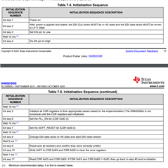
Additionally It is vital that you follow the startup procedure on this device. The procedure is as follows:

Let me know if you have any more questions.
Best,
Vishesh Pithadiya