This thread has been locked.

If you have a related question, please click the "Ask a related question" button in the top right corner. The newly created question will be automatically linked to this question.

DS250DF230EVM: Inquiries regarding switching with/without RetimerCDR function

Part Number: DS250DF230EVM
Other Parts Discussed in Thread: SIGCONARCHITECT, DS250DF230

Using the DS250DF230EVM, I am trying to compare the BER performance of an optical module (DUT) currently under development with and without the RetimerCDR function.
Therefore, please answer the following questions.

(Question 1)
In this case, in order to switch with/without the RetimerCDR function in SigConArchitect, turn on/off the "Enable" button of "PRBS Generator Configurators" in the "PRBS Gen/Checkr" tab of "High Level Page". Should I do that?

Also, if the above method is incorrect, please let me know the correct method.


(Question 2)
When the “Enable” button of “PRBS Generator Configurators” is ON, is the Tx output data the same data that is regenerated by RetimerCDR based on the DUT output data?
Or is it completely new PRBS data that is generated by extracting only the clock based on the DUT output data (in other words, data that is completely different from the DUT output data)?

(Question 3)
Regarding Tx output data with CDR locked, what is the difference between turning on the "Enable" button in "PRBS Generator Configurators" and turning it off?
(This question may be similar to questions 1 and 2, but please answer.)


Thank you for your support.

  • Hi Ohyama-san,

    Would it be possible to share a block diagram of your test setup?  This helps us more effectively answer your questions.

    Reading over your description, my understanding is that you're generally trying to understand if the retimer CDR function is improving your BER.  Is my understanding correct?  Please keep in mind that even if retimer CDR is bypassed, the retimer will still apply CTLE to the signal it receives.

    Question 1:

    In order to enable or disable the retimer CDR functionality, you should adjust the pre and post lock outputs in the CDR tab of the high level page. The pre-lock output controls the retimer output prior to CDR lock, and the post lock output controls the output after CDR lock.  By default, pre-lock output is "mute", and post-lock output is "retimed data".

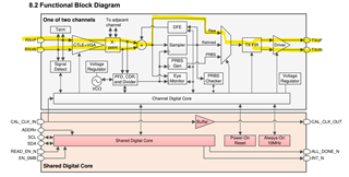
    In order to bypass the retimer CDR functionality, you can set the pre-lock and post-lock output setting to "raw data mode".  By making these changes, once the retimer detects a signal on its input, it will output a non-retimed copy of the signal. This will bypass the retimer CDR, as shown in the block diagram below.

    Question 2:

    When the "Enable" button of the "PRBS Generator Configurations" is ON, the retimer generates completely new PRBS data, using the recovered clock from its input signal.  In other words, the data the retimer outputs is completely different from the data it is receiving.

    Question 3:

    When the "Enable" button of the "PRBS Generator Configurations" is ON, the retimer generates PRBS data.  This can be useful if you are trying to identify where there are errors in a link.

    For example, if you have a link from ASIC 1 --> Retimer--> ASIC 2 and you are observing bit errors on ASIC 2, you don't have a clear indicator as to what section of the link is creating bit errors.  If you enable the retimer PRBS generator, you can check if the link from Retimer --> ASIC 2 has any bit errors.  Additionally, by enabling the retimer PRBS checker, you can check if the link from ASIC 1 --> Retimer has any bit errors.

    Thanks,

    Drew

  • Hi, Drew,
    Thank you for your prompt and very thorough response.

    Regarding my question, your understanding is correct. It seems like my understanding was wrong about how to enable or disable the Retimer CDR function, and I now understand it thanks to your answer to question 1.

    For further understanding, here is a block diagram that I would like to evaluate as you would like.

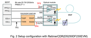
    Figure 1 shows the original setup configuration, in which TOSA and ROSA of the optical module are connected in loopback using optical fiber, and the BER characteristics are evaluated.

    Figure 2 shows the setup configuration that we would like to implement, with RetimerCDR installed after ROSA. This time, channel-0 of DS250DF230EVM is used.

    First, Figure 1-A shows the eye waveform observed at test point TP1 of the ROSA output in Figure 1.

    Next, in the configuration shown in Figure 2, and according to your comment, set the "Pre-LOCK Output" setting on the "CDR" tab to "Mute" and the "Post-LOCK Output" setting to "Retimed Data". Figure 2-A shows the eye waveform observed at test point TP2, which is the output of RetimerCDR.

    For reference, Figure 2-B shows the waveform at test point TP2 when the RetimerCDR function is bypassed ("Pre-LOCK Output" and "Post-LOCK Output" settings are set to "Raw data mode"). From the differences in Figure 1-A, Figure 2-A, and Figure 2-B, we have confirmed that by inserting RetimerCDR after ROSA, a clear eye opening can be obtained. I was able to fully understand. thank you.

    However, one problem became apparent here.
    When evaluating the BER characteristics, there is no improvement in the BER characteristics regardless of whether RetimerCDR is used or not.
    The minimum error-free received optical power of this optical module without Retimer CDR (Figure 1-A or Figure 2-B) is approximately -2.8 dBm. On the other hand, the minimum error-free received optical power with RetimerCDR (Figure 2-A) is also around -2.8dBm. In other words, there is no improvement in BER characteristics regardless of whether RetimerCDR is used or not.

    By the way, if the input light is further reduced to -6 dBm using a variable optical attenuator, in the case (without RetimerCDR) of Figure 1, the eye waveform will be further buried in noise as shown in Figure 1-C. On the other hand, in the case (with RetimerCDR) of Figure 2, the eye waveform is still clearly reproduced and observed as shown in Figure 2-C.

    Although the eye waveform has been observed to be greatly improved, I do not understand why the BER characteristics are not improved even with RetimerCDR.


    So, is there any way to set up the DS250DF230EVM to perform BER measurements?

    If you have any experience or know anything, please let me know.

    Thank you very much for your support.

  • Hi Ohyama-san,

    Thanks sharing your block diagram and test results.  This is very helpful!

    What BER are you observing?  Is there a significant difference in BER between the different test cases?

    I think we need to work to identify what part(s) of the link are resulting in BER.  I have a couple questions related to this.

    • What is the insertion loss between your BERT and optical module?
    • Can you enable the PRBS checker on the DS250DF230EVM?  This can be done through High Level Page --> PRBS Gen/Checker --> PRBS Checker --> Turn ON.  Does the DS250DF230EVM report BER similar to your BERT?
    • When the DS250DF230EVM PRBS generator is enabled, what BER does your BERT measure?
    • When the DS250DF230 is receiving data (PRBS gen/checker disabled), can you share a register dump?  This can be done by using the "save to file" option in SigCon Architect.  This register dump will have information about the HEO/VEO that the DS250DF230 measures and the RX EQ settings it is using.

    Thanks,

    Drew

  • Hi Drew-san

    Thank you for your response.
    I will answer each of the following questions.


    >(Q1) What is the insertion loss between your BERT and optical module?
    (A1)
    We have not actually measured the insertion loss of the high frequency cable used between the BERT and the optical module, so please allow us to share the specification information.
    THORLABS_2.92 mm-to-2.92 mm Microwave Cables_KMM12 (L=305 mm)

    Thorlabs - KMM12 Microwave Cable, 2.92 mm Male to 2.92 mm Male, 12" (305 mm)

    Also, when further connecting DS250DF230EVM,
    We use the recommended "Huber+Suhner 1x8 MXP (MF53/1x8A_21MXP/21SMA/152) cable assemblies".

    >(Q2) Can you enable the PRBS checker on the DS250DF230EVM? This can be done through High Level Page --> PRBS Gen/Checker --> PRBS Checker --> Turn ON. Does the DS250DF230EVM report BER similar to your BERT?

    (A2)
    The measured results are shown in the table. I think the BER of both is similar.
    However, with the DS250DF230EVM's PRBS checker, it seems that when the number of errors reaches 2047, it becomes saturated and the measurement stops. Is this normal behavior?

    >(Q3) When the DS250DF230EVM PRBS generator is enabled, what BER does your BERT measure?

    (A3) In this case, our BERT is error-free up to an input optical power of around -6.5dBm.
    If it is less than that, a synchronization error will occur and measurement will not be possible.

    >(Q4) When the DS250DF230 is receiving data (PRBS gen/checker disabled), can you share a register dump? This can be done by using the "save to file" option in SigCon Architect. This register dump will have information about the HEO/VEO that the DS250DF230 measures and the RX EQ settings it is using.

    (A4)
    I am attaching the requested register dump file.
    20240216_ohyama_Pin=-3.0dBm.cfg
    This is when the input optical power is -3.0dBm.

    20240216_ohyama_Pin=-3.0dBm.cfg

    Please give us your analysis.
    Thanks.

  • Hi Ohyama-san,

    Thanks for your thorough response.

     As reference points, I have added a couple more test points to your block diagram.

    I'd like to share my thoughts about where errors are most likely occurring in this test setup.

    TP3:

    Due to the low insertion loss of the cables used between your BERT and optical module, I believe it's unlikely that any bit errors would be present at TP3.  I am assuming that the electrical characteristics of your BERT signal (i.e. signal amplitude) correspond to recommended optical module receiver electrical characteristics.

    TP2:

    Your testing shows that enabling the PRBS generator on the DS250DF230EVM results in no errors on the BERT for input optical power down to around -6.5 dBm.  This is a good indicator that the link between the DS250DF230EVM TX and BERT RX is operating without any errors.

    TP4:
    Based on test results so far, I believe errors are occurring due to the electrical signaling characteristics at TP4.  I have a couple supporting data points for this.

    • BER measurements taken at TP1 are comparable to retimer BER measurements (prior to prbs error checker saturation at 2047).
      • Related to "However, with the DS250DF230EVM's PRBS checker, it seems that when the number of errors reaches 2047, it becomes saturated and the measurement stops. Is this normal behavior?" : The retimer has an 11 bit error counter, so this is expected behavior.
    • Based on your register dump, the DS250DF230 internal eye monitor measures an eye opening of about 0.4 UI and 84 mV.  Empirically, we have observed good BER performance on our 25G retimers with an internal eye measurement of 0.4 UI and 200 mV.  We typically try to target an eye opening of around 200 mV or better.
    • Looking at eye measurements at TP1, it appears the signal amplitude is relatively small, <200mVpp.  This is consistent with the retimer eye opening measurement.

    Can you confirm if your eye measurements at TP1 and TP2 are differential measurements?

    Suggested Experiments:

    In order to improve BER, I have a couple of experiments.  In general, my thought process is to adjust the DS250DF230 receiver to better handle the signal from your optical module.  Is it possible to try these experiments and see if your BER improves?

    For each of these experiments, after making changes to the RX EQ settings, I would recommend pressing the "Reset CDR" button in SigCon Architect.  This will cause the retimer to reset its CDR state machine.  The reason for this is that resetting the CDR state machine will cause the retimer to re-adapt its RX equalization settings.

    1) Under High level page --> RX EQ/DFE, can you select "Enable VGA selection bit"?  Also, please confirm "Enable eq_hi_gain" is also selected.  Selecting these bits increases the DC gain of the DS250DF230 RX equalization.  This setting is recommended for an input signal <600mVpp.  I would recommend enabling these settings for additional experiments unless otherwise noted.

    2) Under High Level Page --> RX EQ/DFE, can you select "Boost 3 limiting bit"?  This bit enables the final CTLE boost stage to act as a limiting amplifier.  This creates a non-linear signal chain, but may be useful due to the low input amplitude of the signal.

    3) Under High Level Page --> RX EQ/DFE, can you select "Adaptive Mode 2" and "Enable DFE"? You may also need to press the "adapt DFE taps" button.  This setting enables DFE on the retimer.  This equalization stage can be useful in equalizing signal impairments that CTLE cannot compensate for.  I would not recommend using this setting with the "boost 3 limiting bit" enabled as DFE requires a linear signal chain in order to operate correctly.

    4) Do you have the ability to adjust the amplitude of the signal from your optical module?  If there is any setting that can increase this, I would recommend trying this setting to see if this can improve BER.

    Thanks,

    Drew

  • Hi Drew-san,

    Thank you for your detailed comments.

    First, I'll answer your questions.


    (A1)
    Regarding "Can you confirm if your eye measurements at TP1 and TP2 are differential measurements?", the oscilloscope we are using (Anritsu MP2110A) does not support differential measurements when observing eye waveforms. When measuring the eye waveform, I connect the P-channel to the ED(+) input and the N-channel to the oscilloscope input.

    (A2)
    Regarding "Do you have the ability to adjust the amplitude of the signal from your optical module?", there is no such adjustment. It's just the direct signal coming out from ROSA's built-in TIA.

    Now, we will try implementing your "Suggested Experiments" at the beginning of the week. Before that, let me confirm a few things.

    (Q1)
    In the paragraph "TP4" of your description, is "TP1" correct in "BER measurements taken at TP1 are comparable to ...."? I thought this was referring to TP2?

    (Q2)
    Regarding "Empirically, we have observed good BER performance on our 25G retimers with an internal eye measurement of 0.4 UI and 200 mV. We typically try to target an eye opening of around 200 mV or better."
    In other words, does the DS250DF230 require an Rx input signal that has an amplitude of at least 200mV when measured by the internal eye monitor function?

    (Q3)
    Regarding "Looking at eye measurements at TP1, it appears the signal amplitude is relatively small, <200mVpp. This is consistent with the retimer eye opening measurement."
    In other words, the amplitude of the eye waveform (Fig1-A) measured by TP1 is only 121.6mV, and since cables and connectors are also added to the Rx connection of DS250DF230, the amplitude observed by the internal eye monitor function has decreased to 84mV. Is that what you are pointing out? (Please let me confirm just to be sure.)

    (Q4)
    Even though the eye waveform observed at TP1 (Figure 1-A) is clearly improved to the eye waveform observed at TP2 (Figure 2-A) using the DS250DF230EVM, What is happening is that the BER measurement is still not improved. Does this mean that it is not possible to clearly improve the BER characteristics by simply observing the eye waveform? What do you think about this from your experience so far?

    (Q5)
    There are 16 types of "CTLE Boost Settings" for "RX EQ/DFE" settings.
    Is it okay to choose one from these and try it out?

    (Q6)
    Is it the same as not setting anything when "CTLE Boost Settings" is "0"?

    (Q7)
    The steps to change the settings are "Reset CDR" => "(Setting something)" => "Apply to All Channel", right?

    (Q8)
    After performing the setting procedure in "Q7", if the results are reflected in the "EQ Boost" window, is it OK? The 4-digit number sequence in the "EQ Boost" window is the sequence of values 0 to 3 for "Boost Stage", right?


    For reference, in the previous measurements, I selected "Adaptive Mode 1, CTLE Only" in "Adaptive Mode Selection" on the "Rx EQ/DFE" tab. At this time, "Enable eq_hi_gain?" was checked and enabled by default.


    Have a nice weekend!!

  • Hi Ohyama-san,

    Thanks for the detailed response.  Today was a US holiday.  I will get back to you with additional details tomorrow.

    Thanks,
    Drew

  • Hi Ohyama-san,

    (Q1)
    In the paragraph "TP4" of your description, is "TP1" correct in "BER measurements taken at TP1 are comparable to ...."? I thought this was referring to TP2?

    (A1)

    Yes my mistake, TP2 is correct.

    (Q2)
    Regarding "Empirically, we have observed good BER performance on our 25G retimers with an internal eye measurement of 0.4 UI and 200 mV. We typically try to target an eye opening of around 200 mV or better."
    In other words, does the DS250DF230 require an Rx input signal that has an amplitude of at least 200mV when measured by the internal eye monitor function?

    (A2)

    We would typically recommend working to target 200mV when measured by the internal eye monitor.  Although it is possible to have good BER with a signal slightly less than 200mV, we have empirically observed good BER across several operating conditions by meeting 200mV.  Because of this, it is generally our recommended target.

    (Q3)
    Regarding "Looking at eye measurements at TP1, it appears the signal amplitude is relatively small, <200mVpp. This is consistent with the retimer eye opening measurement."
    In other words, the amplitude of the eye waveform (Fig1-A) measured by TP1 is only 121.6mV, and since cables and connectors are also added to the Rx connection of DS250DF230, the amplitude observed by the internal eye monitor function has decreased to 84mV. Is that what you are pointing out? (Please let me confirm just to be sure.)

    (A3)

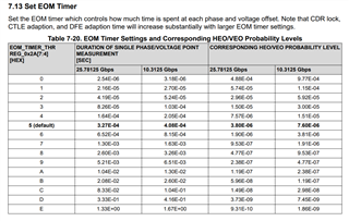
    Yes, this was my general thought.  84mV seems to be roughly in the range of 121mV, especially given some variation in cables and the retimer rx stage.  Also, by default, the retimer eye monitor has a probability level of 4E-6.  I'm not sure how that compares to your scope measurement, but this might be an additional contributing factor.

    (Q4)
    Even though the eye waveform observed at TP1 (Figure 1-A) is clearly improved to the eye waveform observed at TP2 (Figure 2-A) using the DS250DF230EVM, What is happening is that the BER measurement is still not improved. Does this mean that it is not possible to clearly improve the BER characteristics by simply observing the eye waveform? What do you think about this from your experience so far?

    (A4)

    Yes this is correct.  The retimer will output a clean signal, so you will observe a good eye from the retimer.  However, if it's receiving data with errors, or if the retimer is not able to accurately sample the data (i.e. if internal eye measurement is bad), then it will transmit errors in the data.

    (Q5)
    There are 16 types of "CTLE Boost Settings" for "RX EQ/DFE" settings.
    Is it okay to choose one from these and try it out?

    (A5)

    Since you are using adapt modes 1/2, CTLE will be automatically adapted.  However, you are welcome to manually try out different settings.  My expectation is that low values will be appropriate for your case since there is very little insertion loss.  You can enable the CTLE boost override in order to do this.  I'd also recommend reviewing the sequence in the programming guide as this has information about the CTLE bypass used in DS250DF230.

    (Q6)
    Is it the same as not setting anything when "CTLE Boost Settings" is "0"?

    (A6)

    Yes, this is correct.

    (Q7)
    The steps to change the settings are "Reset CDR" => "(Setting something)" => "Apply to All Channel", right?

    (A7)

    If you are doing experiments where the retimer is automatically adapting CTLE/DFE, I would actually recommend "Set something" --> Apply to All Channel --> Reset CDR.  The reason is that resetting CDR will cause the retimer to re-adapt CTLE/DFE.  This guarantees that your changes are being applied correctly.

    (Q8)
    After performing the setting procedure in "Q7", if the results are reflected in the "EQ Boost" window, is it OK? The 4-digit number sequence in the "EQ Boost" window is the sequence of values 0 to 3 for "Boost Stage", right?

    (A8)

    Yes, the 4 digit sequence in EQ boost corresponds to EQ boost stages.

    Thanks,

    Drew

  • Hi Drew-san,

    I have tried the "Suggested Experiments" from you and will report and share the results.

    In "Adaptive Mode 1, CTLE Only", the VEO value of the internal eye monitor when "Enable eq_hi_gain?" was enabled was 85mA when the input optical power was -3.0dBm.
    Next, when I also enabled "Enable VGA selection bit", the VEO value increased to 118mV.
    Furthermore, even if I enabled "Boost 3 Limiting Bit", the VEO value did not increase any further.
    So change to "Adaptive Mode 2,CTLE w/DFE Fine Tune", enable "Enable eq_hi_gain?" and "Enable VGA selection bit", and also disable "Boost 3 Limiting Bit" as you say , the VEO value increased to 150mV. With this setting, we were able to confirm for the first time that the input optical power was error-free from -5.5 to -6.0 dBm.

    However, the most stable and error-free setting was when I selected "13" for the "CTLE Boost Settings" value. At this time, the input power was around -5.5 to -6.0dBm, and the VEO value was around 100mV at most.

    From the above results, it was confirmed that there was at least an improvement of about 3 dB, from the initial error-free level of -3.0 dBm to -5.5 to -6.0 dBm. Thanks to your various guidance, I was able to confirm the minimum operation contents.

    Therefore, please comment further below.

    (Q2-1)
    Considering that the VEO value of the internal eye monitor is currently still far below the recommended 200mV, does this mean that the signal amplitude at the Rx input of the DS250DF230 is low, including the attenuation of the cable etc. from our ROSA output?

    If so, the solution would be to either insert an amplifier before the Rx input, or integrate a DS250DF230 chip immediately after the ROSA, right?

    (Q2-2)
    What is the minimum input signal amplitude specified for the DS250DF230?
    Is it the value of VSDAT in the manual (TYP. 145 mVppd)?

    (Q2-3)
    There are 16 types of "CTLE Boost Settings", but is it only possible to select them manually? Is it not possible to configure CTLE automatically?

    (Q2-4)
    If I select it from "CTLE Boost Settings", isn't that value displayed in the "EQ BOOST" window?

    For example, even if you select "13" from "CTLE Boost Settings", "3", "2", "3", "2" are automatically displayed in light text in "Boost Stage 0 to 3", respectively. However, the "EQ BOOST" window only displays "0000" or "1000". Is this the correct setting?

    (Q2-5)
    What is the difference between "Adaptive Mode 2, CTLE w/DFE Fine Tune" and "Adaptive Mode 3, DFE w/CTLE Fine Tune"?

    This is my first time testing a Retimer chip, so please bear with me a little longer.

    Thank you.

  • Hi Ohyama-san,

    Thanks for the update.  I'll get back to you early next week with responses to your questions.

    Thanks,
    Drew

  • Hi Ohyama-san,

    So change to "Adaptive Mode 2,CTLE w/DFE Fine Tune", enable "Enable eq_hi_gain?" and "Enable VGA selection bit", and also disable "Boost 3 Limiting Bit" as you say , the VEO value increased to 150mV. With this setting, we were able to confirm for the first time that the input optical power was error-free from -5.5 to -6.0 dBm.

    Thanks for the update on this.  It sounds like the DFE added by adapt mode 2 had a significant impact on performance.

    (Q2-1)
    Considering that the VEO value of the internal eye monitor is currently still far below the recommended 200mV, does this mean that the signal amplitude at the Rx input of the DS250DF230 is low, including the attenuation of the cable etc. from our ROSA output?

    If so, the solution would be to either insert an amplifier before the Rx input, or integrate a DS250DF230 chip immediately after the ROSA, right?

    (A2-1)

    I believe that the low signal amplitude is inherent to your optical module.  My understanding is that often, optical modules have a limiting amplifier in order to increase signal amplitude after the TIA.  Something like this could be helpful.

    With that said, if you're able to observe good BER across a range of operating conditions with the DS250DF230, it's possible that additional devices might be unnecessary.

    (Q2-2)
    What is the minimum input signal amplitude specified for the DS250DF230?
    Is it the value of VSDAT in the manual (TYP. 145 mVppd)?

    (A2-2)

    Yes, this is the typical minimum signal amplitude required in order to trigger the "signal detect" circuit in the DS250DF230.  The signal detect status is used to enable downstream functional blocks in the retimer.  There is a register that can force the signal detected state (ch_reg_0x14[7]), but I have not seen this used in a typical application.  If the retimer signal detect status is not set, I expect it would be challenging to achieve good BER on such a low amplitude signal.

    (Q2-3)
    There are 16 types of "CTLE Boost Settings", but is it only possible to select them manually? Is it not possible to configure CTLE automatically?

    (A2-3)

    CTLE is set automatically in adapt modes 1, 2, and 3 unless CTLE boost override is set.  Are you observing better eye values when manually selecting CTLE?

    (Q2-4)
    If I select it from "CTLE Boost Settings", isn't that value displayed in the "EQ BOOST" window?

    For example, even if you select "13" from "CTLE Boost Settings", "3", "2", "3", "2" are automatically displayed in light text in "Boost Stage 0 to 3", respectively. However, the "EQ BOOST" window only displays "0000" or "1000". Is this the correct setting?

    (A2-4)

    Are you setting the CTLE boost override?  It sounds like CTLE boost settings are not being applied.

    (Q2-5)
    What is the difference between "Adaptive Mode 2, CTLE w/DFE Fine Tune" and "Adaptive Mode 3, DFE w/CTLE Fine Tune"?

    (A2-5)

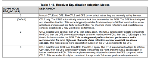
    Please see the table below for details on the differences.  At a high level, adapt mode 3 emphasizes the use of DFE for equalization compared to adapt mode 2.

    Thanks,

    Drew

  • Hi Drew-san,

    Thank you for pointing it out.
    I may have had some misunderstanding regarding "CTLE Boost Settings".

    (Q1)
    "CTLE Adapt Modes 1, 2, and 3" are automatically set unless a CTLE boost override is configured, right?
    Is the CTLE Stage setting state when it is automatically set displayed in the "EQ Boost" window?

    (Q2)
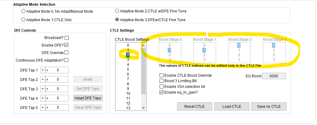
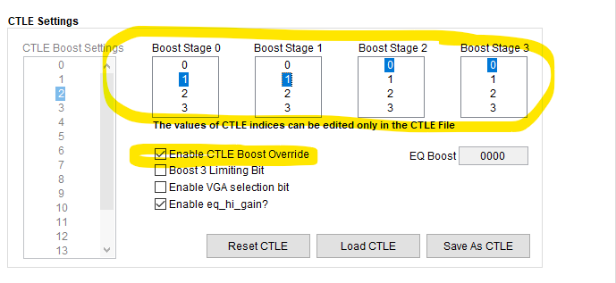
    If you want to enable "CTLE Boost Settings" which has 16 settings menu, your instructions are to enable "CTLE Boost Override". However, if "CTLE Boost Override" is enabled, "CTLE Boost Settings" will be in light text and cannot be selected.

    For example, if "CTLE Boost Override" is disabled and you select "9" in "CTLE Boost Settings", "Boost Stage 0 to 4" at that time will be "3,1,2,0" in light text.
    And here, if you enable "CTLE Boost Override", "3,1,2,0" will be cleared in the "Boost Stage 0 to 4" display. In other words, it seems that the "CTLE Boost Settings = 9" setting is canceled.
    Is there something wrong with my configuration steps?

  • Hi Ohyama-san,

    I'll get back to you on your questions tomorrow, thanks for your patience.

    Thanks,

    Drew

  • Hi Ohyama-san,

    Apologies for the delay.

    (A1)

    I think there may be an issue where the EQ Boost displayed in the "Rx EQ/DFE" tab does not get updated correctly.  However, I expect the EQ Boost displayed in the "Device Status" tab to be accurate.

    (A2)

    Apologies for the confusion on this. The CTLE boost override does not allow selection of different indexes and instead allows you to directly set the CTLE boost value.  My recommendation is to use different index selections to see what the default boost settings are, then manually set these using the "Enable CTLE boost override" option.

    When CTLE boost override is not set, selecting the different CTLE boost settings in SigCon Architect does not have an impact on the device.

    Thanks,

    Drew

  • Hi Drew-san,

    If you say "When CTLE boost override is not set, selecting the different CTLE boost settings in SigCon Architect does not have an impact on the device.", it seems that the result that I previously reported on February 23rd, "the most stable and error-free setting was when I selected "13" for the "CTLE Boost Settings" value." was incorrect. This is because "CTLE boost override" was not enabled at this time. Perhaps CTLE at this time was a result of being automatically set.

    Thank you for everything.
    From now on, I will try various things.

  • Hi Ohyama-san,

    Thanks for the update.

    I hope you've been able to resolve the bit errors you were observing.  Please let us know if you need any additional support.

    Thanks,

    Drew