This thread has been locked.

If you have a related question, please click the "Ask a related question" button in the top right corner. The newly created question will be automatically linked to this question.

Routing passthrough ethernet connections

Other Parts Discussed in Thread: TPS2372, STRIKE, TPS23861

I have a design that uses the TPS2372 and TPS23861PW to implement a PoE "daisy chain" application.  I have worked with the TI Power engineers and have recevied valuable feedback on the PoE portion of the design.  They suggested I work with this forum for my remaining PHY questions.

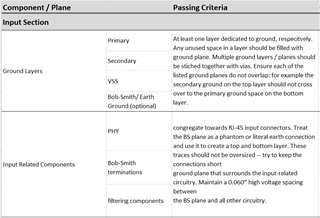
The design has 2 ethernet paths:  a passthrough; the PoE connection.  My questions are in regards to routing the Ethernet differential pairs and the ground planes underneath.  The attached Word document lists my questions.  I can also provide Altium files and/or Gerbers if necessary.

Any help will be greatly appreciated.

  TI Questions asked during initial submission.docx

  • Hi David,

    Sorry for the delay on this. Which PHY are you using?

    Thank you,

    Evan

  • Evan -

    I might not be understanding your question.  We are NOT using any PHY IC.  All of the actual ethernet data pair lines are passed through the PCBA without being used.  We are ONLY using the Ethernet for PoE.  My questions relate to HOW to route those lines correctly, as we are NOT using them.  I think the Word document that I provided provides a pretty good description of what we are doing.

    Let me know if I mis-answered your question.

  • Hi David,

    Thanks for clarifying, some layout recommendations are PHY-dependent so I wanted to confirm this ahead of any suggestions.

    I am discussing your queries with the team, please expect a follow-up by tomorrow.

    Best regards,

    Evan

  • Evan -

    Thanks.  I can email you Altium files if you would like/it would prove helpful.

  • Hi David,

    Sure, that would help add more context. Please share at e-mayhew@ti.com .

    Thanks again,

    Evan

  • Evan -

    I sent you the files via the email link you provided.  Let me know if you have any issues with them.

  • Hi David,

    Thank you for sharing the files.

    Regarding question #1, it is recommended to have a solid ground plane under the MDI traces for impedance control and current return path.

    Regarding question #3, can you share the references you note about this transformer connection being okay? I have not seen this before, so I would like to take a look and verify as well.

    For question #2, I am discussing with the team about possible impedance issues with this pass-through connection. Please expect feedback tomorrow or early next week on this note.

    Here is a good layout checklist for PHYs, although only the notes on MDI traces may be relevant for you here:

    https://www.ti.com/lit/zip/snlr048

    Best regards,

    Evan

  • Evan -

    Regarding question 1 - I understand the recommendation.  However, my question is "what ground"?  As we are not actually using any of the signals on our board, what do I reference the "ground plane" to?  Do I use the POE ground?  Do I use shield ground?  Do I just use an unconnected piece of copper?  Something else?

    Regarding question 3 - Check out these 2 links.  There are others, but these are the two I have listed on the schematic
    https://e2e.ti.com/support/interface-group/interface/f/interface-forum/544013/dp83867-magnetics-connection
    https://microchip.my.site.com/s/article/Can-the-Ethernet-transformer-pairs-be-swapped

    Let me know if you need anything else.

  • Hi David,

    Evan is on time bank until Tuesday March 5th. Please allow him until then to continue supporting you.

    Regards,

    Alvaro

  • Will do.  Thanks Alvaro.

  • Hi David,

    Thank you for your patience. I should have feedback for you by tomorrow.

    Regards,

    Evan

  • Hi David,

    I have a couple corrections after discussing with team:

    1,2) If the PoE traces are only carrying power, then it is okay to not have a ground plane reference underneath. The impedance discontinuity of J7/J8 pass-through connection is also not a concern if the traces only carry power.

    3) Can you clarify the purpose of back-to-back transformers in your application? 

    Thank you,

    Evan

  • Evan

    There seems to be a misunderstanding of the system.  I appologize for the confusion.  Below are the answers to your questions.  In order to speed up the communication loop and avoid misunderstandings, if you would like to do a call, we could do that as well.

    1,2) If the PoE traces are only carrying power, then it is okay to not have a ground plane reference underneath. The impedance discontinuity of J7/J8 pass-through connection is also not a concern if the traces only carry power.
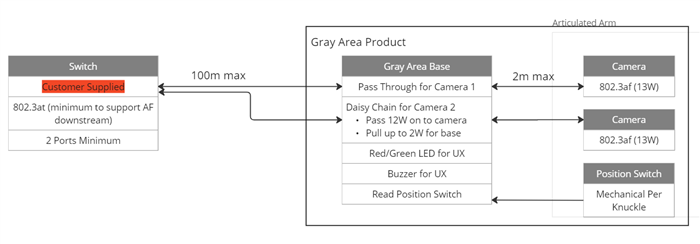
    They are NOT only carrying power.  BOTH sets of ethernet traces are sending/receiving data with downstream devices.  Maybe this block diagram will help.

    Our PCBA sits between an upstream switch and two downstream cameras. There are two ethernet connections between the switch and the cameras (one connection for each camera).

    Our device pulls power AND NOTHING ELSE from one of the ethernet connections.  However for BOTH connections the data must traverse our PCBA in both directions so that the Switch/Cameras can communicate with each other.


    3) Can you clarify the purpose of back-to-back transformers in your application? 

    My understanding is that we need magnetics for each ethernet connector to have isolation on the data lines for both upstream and downstream connections.  If not, can you please show me what I need to do.
    NOTE:  The TI PoE team has verified that the two transformers are correct.  However, there might be a misunderstanding.


  • Sorry for the confusion here, and thank you for further clarifying.

    Regarding (2), the impedance discontinuity of the connector is a concern.

    For our PHY applications, we recommend <3 inches of trace length from the MDI trace to the magnetic before the RJ-45 connection. This assumes the link partner's MDI also follows similar MDI trace length, to avoid any concerns with impedance discontinuity affecting the data. Is this pass-through connection required, or are there other possible approaches?

    For (3), I agree with PoE team that this looks correct.

    Please allow me some time to confirm the correct ground reference plane for (1) and (2).

    Thank you,

    Evan

  • Hi David,

    For (1) and (2), this is the ground plane recommendation we have for PoE/PoDL with our PHYs:

    - Before the magnetic (on PHY-side), use board/digital ground as reference plane under MDI traces.

    - After the magnetic (connector-side), use connector ground as reference plane under MDI traces.

    - No ground plane under magnetics

    The goal is to isolate the PHY ground from the connector ground to protect from ESD events, but it is unclear to me how to apply this methodology to your design.

    Thank you,

    Evan

  • Evan -

    The goal is to isolate the PHY ground from the connector ground to protect from ESD events, but it is unclear to me how to apply this methodology to your design.

    Hmm. . . is there someone else at TI that might know?  I am unsure what I am supposed to do now with the information thus far provided. . .  

  • Hi David,

    I discussed this further with the team. Chassis ground should be used as the reference plane under ethernet pass-through traces on both sides of T1/T2 transformers. My main concern here is possible damage to TPS2372 / TPS23861 in the event of an ESD strike on the connector, but as they are referenced to a different ground I believe this is not an issue.

    I have redirected to power team to confirm if they agree with this reasoning.

    Thank you,

    Evan

  • Thank you Evan.  I will wait to hear from the power team before I close the ticket then.

  • Hi Evan,

    Thanks for your help to address the PHY related questions!

    Hi David,

    For the Ethernet connector ground (chassis ground in your case), I think you can leave > 0.06" distance with PoE routings 

    Best regards,

    Diang

  • Hi David,

    I will close this thread for now. Please reply or open a new thread if you have further questions or concerns.

    Best regards,

    Diang