This thread has been locked.

If you have a related question, please click the "Ask a related question" button in the top right corner. The newly created question will be automatically linked to this question.

DP83849I: DP83849I - Flexible Port Switching with RMII application

Part Number: DP83849I

Hi, This is Volkan greetings from Istanbul
In my general embedded applications requiring Ethernet connectivity to expand.
I have an MCU with a single MAC and I can able communicating with the PHY via RMII Ethernet interface. (STM32H7 and LAN8742A)
I decided to use the DP83849I to expand from Single MAC RMII interface to 2 physical RJ45 ports.

Regarding to the AN-1509 PhyterDual Flexible Port Switching application note, i have a couple of questions;
I would like to implement section 3 (Page15) called ''Implementing Flexible Port Switching'' with RMII interface (not MII) so;
- Regarding to this implementing If I want to connect only MAC-A' s (or only MAC-B's ) RX and TX pins via RMII interface, This mean I can able to communicate with both PHY-A and PHY-B ports as transmitter and receiver of Dual PHY at the same time ? (some delays may ignored)
If yes;
- Lets say,If I set RBR[12:11] to ''10'' in Table 1. RX Mapping Controls, I need to set Ports Desired RX MAC Destination to ''Both''. So What should I set in Table 2. RX Port Mapping Configurations, should it be '10' for both ports ?
- Regarding to this matter, Table 3.(Page16) What do I need to set appropriate config i the TX Port Mapping Controls section ?
- In order to get precise process and establish right configuration, Could you please tell me the necessary pin connections, register map and configuration settings with RMII interface from scratch ?
I would be very grateful if you could reply with your valuable information and suggestions.
Best Regards
Volkan Y.
Hardware Developer

  • Hi Volkan,

    Greetings from Santa Clara, thank you for your query!

    Could you please share a block diagram with your intended application with DP83849? I'd like to confirm the requirements and connections before suggesting the device configuration.

    Thank you,

    Evan

  • Hello Evan, nice to meet with you. Thank you for the support. I ve not draw schema abouth the DP83849 connections yet.
    In order to check it out in more detailed,I ve just ordered DP83849IVS-EVK demonstration board. In soon i will provide you block diagram and requirement in here.I can't wait to jump into it.

  • Sounds good, excited to look at your system!

    Any high-level block diagram with the intended port switching will help me understand for suggestions.

    Thank you,

    Evan

  • Hello, have a good weekend.
    I'm so excited to establish my system too. Until my DP83849IVS-EVK Demonstration board arrives, I would like to share with you the block diagram of my application 

    I hope I can make it simple and precise way.


    My questions at this point are;


    - Does Block diagram in the above match for Flexible Port Switching application ?

    - Is DP83849I the right choice for this application ? I will use it instead of LAN8742A . As far as i know there is no DP83849I driver and LAN8742A Drivers does not compatible with DP83849I . According to my reseach on the forum DP83849I driver compatible with DP83848 even if it has single PHY Port. Is that correct ?

    - Considering that this system works properly and the correct components are used, can communication be provided at 100 meters and above?

    - Considering that there is 1pcs DP83849I unit in each client, How many maximum pcs of DP83849I can able to be in a single network in the application ? Is there any node limitation on the network bus ?

    - When each client in the network is connected to each other as in this diagram, Client 1 will also receive the Scan_response sent from Client 2, right ? If yes, I need to evaluate this on the software. Am I right?

    - If everything in the above can able to done to my application and In order to get precise process and establish right configuration, Then Could you please tell me the necessary pin connections, register map and configuration settings, and also which issues I should pay attention to, installation settings, and operation side from scratch ?

    Due to avoid dynamicaly change mux configuration condition, I can able set the PHY ports as fixed purpose.
    Lets say, PortA may be set only for I/O purpose and PortB only for pass through purpose or vice versa.

    Any suggestion, thought, opinion and recommendation is important to me :)
    I would be very grateful if you could reply with your valuable information and suggestions.

    Best Regards
    Volkan

  • Hi Volkan,

    I will be back in office tomorrow. Looking to give feedback on above notes then.

    Thank you,

    Evan

  • Hello Evan,
    I am glad to hear from you. I look forward to your feedback 
    I added somethings to what I wrote in above. I hope I won't bore you with my unlimited questions.:)
    Thank you
    Volkan

  • Hi Volkan,

    Apologies for the delay on my feedback. Unfortunately the block diagram link shared is blocked on TI network - could you embed the image or email the file at e-mayhew@ti.com ?

    So far, I believe the intended application with DP83849 is feasible, but I would like to carefully review the diagram before confirming this.

    Does Block diagram in the above match for Flexible Port Switching application ?

    Pending diagram share.

    According to my reseach on the forum DP83849I driver compatible with DP83848 even if it has single PHY Port. Is that correct ?

    I have seen the same E2E post suggest this, but please note we have not validated the DP83848 driver on DP83849. Worst case, DP83848 driver acts as a reference to develop 849 driver.

    Considering that this system works properly and the correct components are used, can communication be provided at 100 meters and above?

    Yes, cable reach of at least 100m is expected with correct components and layout.

    Considering that there is 1pcs DP83849I unit in each client, How many maximum pcs of DP83849I can able to be in a single network in the application ? Is there any node limitation on the network bus ?

    I do not believe there is any limitation (aside from finite addresses for PHY control). If possible, please include the intended multi-node setup in the diagram so I may confirm.

    When each client in the network is connected to each other as in this diagram, Client 1 will also receive the Scan_response sent from Client 2, right ? If yes, I need to evaluate this on the software. Am I right?

    What is scan_response? I assume this is on the software end, as I have not seen it referenced in datasheet/appnotes.

    If everything in the above can able to done to my application and In order to get precise process and establish right configuration, Then Could you please tell me the necessary pin connections, register map and configuration settings, and also which issues I should pay attention to, installation settings, and operation side from scratch ?

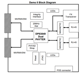
    For now, please refer to DP83849-EVK for the connections. I also recommend ordering this EVK to validate your intended application:

    Thank you,

    Evan

  • Evan thank you for your response, i ve sent you block diagram and some information abouth the software side. I ve also already ordered DP83849IVS-EVK board to validate my intended application.
    I hope to block diagram can give information about the application I want to do.
    Best Regards
    Volkan

  • Hi Volkan,

    Thank you for sharing the details, the application is clearer to me now.

    - Regarding to this implementing If I want to connect only MAC-A' s (or only MAC-B's ) RX and TX pins via RMII interface, This mean I can able to communicate with both PHY-A and PHY-B ports as transmitter and receiver of Dual PHY at the same time ? (some delays may ignored)

    Yes, this is possible from my understanding.

    Lets say,If I set RBR[12:11] to ''10'' in Table 1. RX Mapping Controls, I need to set Ports Desired RX MAC Destination to ''Both''. So What should I set in Table 2. RX Port Mapping Configurations, should it be '10' for both ports ?

    This looks correct to me.

    - Regarding to this matter, Table 3.(Page16) What do I need to set appropriate config i the TX Port Mapping Controls section ?

    From my understanding of your requirements, MAC A should be the TX data source for both Port A and Port B. In this case, Port A RBR[10:9] = '00', and Port B RBR[10:9] = '01'.

    One uncertainty to me are these two requirements being met with one static configuration:

    * packets from MAC A should be sent via RMII to the Host PC via Port A and to the other clients via Port B
    * packets received at Port A from the Host PC should be sent to MAC A via RMII and to the other Clients in the network via Port B

    As there are two possible TX data sources for Port B (MAC A or Port A), I need to confirm if the PHY must be configured dynamically to mux this channel as needed. I have the EVM in hand, please allow me some time to test and confirm.

    Thank you,

    Evan

  • Evan
    First of all, thank you very much for your detailed explanation. Everything is clearer now. You explained it in detail almost like an application note.
    Regarding to my block diagram, about the RX Port Mapping Configuration part;
    If i  understood correctly, when the RBR[12:11] bits are set '10' ( or 00 ) then the incoming data from Port A  will appear in MAC-A. So one time configuration will work at the RX side as i expected.

    But in the TX Side its a little bit different from RX Side.
    However,
    Even though there are two possible TX data sources for Port A (MAC A or/and RX PortB), Port-B's TX signal source should be from only RX-Port A,(not Mac-A).
    Because the task of Port-B is receive incoming data from port itself and send to PortA , this is why its TX data Source should be from RX Port A not from MAC-A..
    So, reletad to the TX Port mapping configuration,

    tx port mapping configuration

    Due to TX source of Ports differences, 
    staticly set of bits RBR[10:9]  ''00'' or ''10 '' will not work as i expected. 
    Am i right ?

    Considering that the other settings are fixed at startup, only for the TX port source;
    RBR[10:9]  bits should remain at ''10 ' and whenever I need to send out data from MAC-A,via Port A I need to set them to ''00'' .
    Is there anything that i missed or misunderstood please let me know. Because I am  a bit confused.:)
    I hope to your EVK test goes well and get some good news. Thank you for your challenge, i appriciated
    Best Regards
    Volkan

  • Hi Volkan,

    Thank you for clarifying.

    Due to TX source of Ports differences, staticly set of bits RBR[10:9]  ''00'' or ''10 '' will not work as i expected. 
    Am i right ?

    I believe your understanding is correct, but I need time to validate on DP83849EVK if dynamic config is required. Please expect a follow-up on this by mid next week, it will take some time to bring-up EVM and run through all test cases for your requirement.

    Thank you,

    Evan

  • Hi Volkan,

    Sorry for the delay here. I need more time to bring-up the EVM. When do you expect to receive the EVM on your end?

    Thank you,

    Evan

  • Hello Evan,
    Nice to hear from you again. Yes according to the planned delivery date, probably this week i will handle the DP83849EVK and MSP-EXP430F5529 dev. as well.
    Thanks for the support
    Best Regards
    Volkan

  • Thanks for confirming.

    Looking to get back to you with feedback ASAP.

    Best regards,

    Evan

  • Hello Evan, i wish you have wonderfull weekend,
    As part of the dynamic config requirement issue, what abouth if I would like to change mode settings by strapping option ?
    I am aware that thanks to Strap pin feature initialize registers itself. I assume that I set the registers at the first start, then Lets say, when I pull up the Strap pin while it is default settings Pull Down, does it manipulate the registers immediately? And when you bring it back to the default value, do the registers take its previous state ?
    If not is there any trick or method to do that ?  Do i need hardware or software reset to do this ? What is strapping timing ? Or can you please provide me more details, or refer to app note abouh strap pin feature ?
    Best Wishes
    Volkan

  • Hi Volkan,

    That is correct, with minimum reset pulse width of 1us, the straps will re-initialize after total 4us.

    Can you clarify how you intend to use straps for dynamic configuration? The voltage is sampled at the pin on reset to determine the strap value, so switching the config would require an analog component capable of changing the resistance seen at the pin before reset (resistance changed dynamically based on switching logic).

    It may be simpler to implement firmware with logic to control this dynamic config via register writes.

    Thank you,

    Evan

  • Hello evan,
    Thank you for your response, Strap pin will Controll by The MCU which Control the MAC as well. If my scenario in the below makes sense, there is no need for any firmware. To be more clarify Let me explain my thoughts.
    My question is;
    Will This scenario work ? :)

    Note: Even if this scenario works well, there will be an total 8us delay in mode changing. A firmware can be written according to this scenario. Which one do you think makes more sense?

    I would be very grateful if you could reply with your valuable information and suggestions.
    Best Regards
    Volkan

  • Hi Volkan,

    This should be possible, although it may be simpler to implement through register writes on MDC/MDIO.

    For my understanding, is it acceptable to interrupt the data stream for your system with PHY reset in order to change states?

    Thank you,

    Evan

  • Hello Evan

    This should be possible, although it may be simpler to implement through register writes on MDC/MDIO.

    Sure everything is more clearer right now.

    For my understanding, is it acceptable to interrupt the data stream for your system with PHY reset in order to change states?

    I am not sure i will look at it at full stream conditions.
    If i change resigters means Transmit source mode at the same time via MDIO then it means there is no any interrupt while streaming ?
    Thanks Volkan

  • Hi Volkan,

    Switching the PHY config via reset straps will have additional delay, as the PHY will need time to initialize and link up after reset.

    Switching the config via MDIO is expected to have some delay, but it is expected to be much less than resetting the PHY.

    If you are able, I recommend evaluating both options to see which is better suited for your system requirements.

    Thank you,

    Evan