This thread has been locked.

If you have a related question, please click the "Ask a related question" button in the top right corner. The newly created question will be automatically linked to this question.

DS90UB635-Q1: Trying to bring up 635/638 pair. Cannot establish backchannel

Part Number: DS90UB635-Q1
Other Parts Discussed in Thread: DS90UB953-Q1EVM, DS90UB954-Q1EVM

It seems to me the first step of getting the FPD-Link III devices running is to establish the backchannel.  I cannot seem to get that far.

I have two custom prototype boards, one with the DS90UB635, one with the DS90UB638.  They have provisions for power over coax, but I have removed the first filter component on each side to eliminate the possiblity of power noise corruption.  The 635 is powered separately.

I do not currently have a CSI sensor attached to the 635 device.  My plan is to verify functionality using the BIST feature.  I can read and write I2C commands to each device using the I2C pins.

When I connect them together, the 635 device does not produce a CLK_OUT and the LINK_DET bit in register 0x52 = 0;  Register 0x03 reports 0x48 indicating it is in CSI-2 Synchronous Mode.

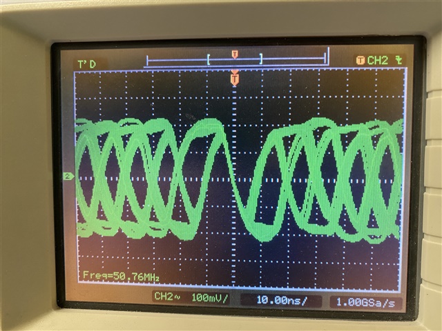
When I connect the 638 coax link directly to a low speed scope I see a reasonable encoded clock signal running at 50Mhz.
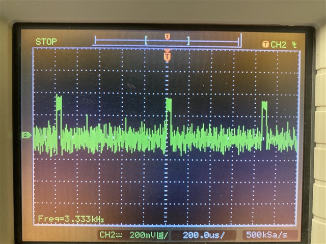
When I connect the scope (with a coax splitter) to the cables between the 635 and 638 I see these odd pulses every ~850µS.  It sure seems like they are generated by the 635.  I do not see any corresponding glitch on the 1.8V supply rail.
Does any of that provide any clues to why the back channel will not connect?

Are there other debugging steps I can take to find this backchannel issue?

  • Now I see that if I continuously read the 635 register 0x52, 10-20% of the time the LINK_DET bit will report 1.

    I still never see any clock on the CLK_OUT/IDX pin.

  • Now I see that LINK_DET still reports 1 10-20% of the time even with the coax cable disconnected.

  • Here is a list of register values read from the 635 and 638 when both devices are powered and connected via coax.

    serdes6.txt
    DS90UB635 Register Read Results
    01.00 = 0x30
    01.01 = 0x00
    01.02 = 0x33
    01.03 = 0x48
    01.04 = 0x00
    01.05 = 0x03
    01.06 = 0x41
    01.07 = 0x28
    01.08 = 0xFE
    01.09 = 0x1E
    01.0A = 0x10
    01.0B = 0x7F
    01.0C = 0x7F
    01.0D = 0xF0
    01.0E = 0x0F
    01.0F = 0x00
    01.10 = 0x00
    01.11 = 0x00
    01.12 = 0x00
    01.13 = 0x00
    01.14 = 0x00
    01.15 = 0x20
    01.16 = 0x18
    01.17 = 0x3C
    01.18 = 0x80
    01.19 = 0x62
    01.1A = 0x62
    01.1B = 0x62
    01.1C = 0x00
    01.1D = 0x00
    01.1E = 0x00
    01.1F = 0x00
    01.20 = 0x00
    01.21 = 0x00
    01.22 = 0x00
    01.23 = 0x00
    01.24 = 0x00
    01.25 = 0x02
    01.26 = 0x00
    01.27 = 0x00
    01.28 = 0x67
    01.29 = 0x33
    01.2A = 0x01
    01.2B = 0x00
    01.2C = 0x00
    01.2D = 0x00
    01.2E = 0x00
    01.2F = 0x00
    01.30 = 0x00
    01.31 = 0x20
    01.32 = 0x09
    01.33 = 0x04
    01.34 = 0x00
    01.35 = 0x00
    01.36 = 0x00
    01.37 = 0x7A
    01.38 = 0x00
    01.39 = 0x00
    01.3A = 0x00
    01.3B = 0x00
    01.3C = 0x00
    01.3D = 0x00
    01.3E = 0x00
    01.3F = 0x00
    01.40 = 0x00
    01.41 = 0x00
    01.42 = 0x00
    01.43 = 0x00
    01.44 = 0x00
    01.45 = 0x00
    01.46 = 0x00
    01.47 = 0x00
    01.48 = 0x00
    01.49 = 0x00
    01.4A = 0x00
    01.4B = 0x00
    01.4C = 0x00
    01.4D = 0x00
    01.4E = 0x00
    01.4F = 0x00
    01.50 = 0x20
    01.51 = 0xC0
    01.52 = 0x20
    01.53 = 0x01
    01.54 = 0x00
    01.55 = 0x00
    01.56 = 0x00
    01.57 = 0x00
    01.58 = 0x07
    01.59 = 0x07
    01.5A = 0x07
    01.5B = 0x00
    01.5C = 0x00
    01.5D = 0x00
    01.5E = 0x00
    01.5F = 0x00
    01.60 = 0x00
    01.61 = 0x00
    01.62 = 0x00
    01.63 = 0x00
    01.64 = 0x00
    01.B0 = 0x04
    01.B1 = 0x4A
    01.B2 = 0x3F
    01.F0 = 0x5F
    01.F1 = 0x55
    01.F2 = 0x42
    01.F3 = 0x39
    01.F4 = 0x35
    01.F5 = 0x33
    DS90UB638 Register Read Results
    00.00 = 0x60
    00.01 = 0x00
    00.02 = 0x1E
    00.03 = 0x20
    00.04 = 0xD3
    00.05 = 0x01
    00.06 = 0x00
    00.07 = 0xFE
    00.08 = 0x1C
    00.09 = 0x10
    00.0A = 0x7A
    00.0B = 0x7A
    00.0C = 0x83
    00.0D = 0xB9
    00.0E = 0x08
    00.0F = 0x7F
    00.10 = 0x00
    00.11 = 0x00
    00.12 = 0x00
    00.13 = 0x00
    00.14 = 0x00
    00.15 = 0x00
    00.16 = 0x00
    00.17 = 0x00
    00.18 = 0x00
    00.19 = 0x00
    00.1A = 0x00
    00.1B = 0x00
    00.1C = 0x00
    00.1D = 0x00
    00.1E = 0x04
    00.1F = 0x02
    00.20 = 0x30
    00.21 = 0x01
    00.22 = 0x00
    00.23 = 0x00
    00.24 = 0x00
    00.25 = 0x00
    00.26 = 0x00
    00.27 = 0x00
    00.28 = 0x00
    00.29 = 0x00
    00.2A = 0x00
    00.2B = 0x00
    00.2C = 0x00
    00.2D = 0x00
    00.2E = 0x00
    00.2F = 0x00
    00.30 = 0x00
    00.31 = 0x00
    00.32 = 0x00
    00.33 = 0x00
    00.34 = 0x40
    00.35 = 0x00
    00.36 = 0x00
    00.37 = 0x00
    00.38 = 0x00
    00.39 = 0x00
    00.3A = 0x00
    00.3B = 0x01
    00.3C = 0x14
    00.3D = 0x6F
    00.3E = 0x00
    00.3F = 0x40
    00.40 = 0x00
    00.41 = 0xA7
    00.42 = 0x71
    00.43 = 0x01
    00.44 = 0x00
    00.45 = 0x00
    00.46 = 0x00
    00.47 = 0x00
    00.48 = 0x00
    00.49 = 0x00
    00.4A = 0x00
    00.4B = 0x12
    00.4C = 0x00
    00.4D = 0x00
    00.4E = 0x02
    00.4F = 0x00
    00.50 = 0x00
    00.51 = 0x00
    00.52 = 0x00
    00.53 = 0x00
    00.54 = 0x00
    00.55 = 0x00
    00.56 = 0x00
    00.57 = 0x00
    00.58 = 0x1E
    00.59 = 0x00
    00.5A = 0x00
    00.5B = 0x00
    00.5C = 0x00
    00.5D = 0x00
    00.5E = 0x00
    00.5F = 0x00
    00.60 = 0x00
    00.61 = 0x00
    00.62 = 0x00
    00.63 = 0x00
    00.64 = 0x00
    00.65 = 0x00
    00.66 = 0x00
    00.67 = 0x00
    00.68 = 0x00
    00.69 = 0x00
    00.6A = 0x00
    00.6B = 0x00
    00.6C = 0x00
    00.6D = 0x7C
    00.6E = 0x88
    00.6F = 0x88
    00.70 = 0x2B
    00.71 = 0x2C
    00.72 = 0xE4
    00.73 = 0x00
    00.74 = 0x00
    00.75 = 0x00
    00.76 = 0x00
    00.77 = 0xC5
    00.78 = 0x00
    00.79 = 0x01
    00.7A = 0x00
    00.7B = 0x00
    00.7C = 0x20
    00.7D = 0x00
    00.7E = 0x00
    00.7F = 0x00
    00.B0 = 0x08
    00.B1 = 0x14
    00.B2 = 0x3F
    00.B3 = 0x08
    00.B4 = 0x25
    00.B5 = 0x00
    00.B6 = 0x18
    00.B7 = 0x00
    00.B8 = 0x8C
    00.B9 = 0x33
    00.BA = 0x83
    00.BB = 0x74
    00.BC = 0x80
    00.BD = 0x00
    00.BE = 0x00
    00.BF = 0x00
    00.C0 = 0x00
    00.C1 = 0x00
    00.C2 = 0x00
    00.C3 = 0x00
    00.C4 = 0x00
    00.C5 = 0x00
    00.C6 = 0x00
    00.C7 = 0x00
    00.C8 = 0x00
    00.C9 = 0x00
    00.CA = 0x00
    00.CB = 0x00
    00.CC = 0x00
    00.CD = 0x00
    00.CE = 0x00
    00.CF = 0x00
    00.D0 = 0x00
    00.D2 = 0x94
    00.D3 = 0x17
    00.D4 = 0x60
    00.D5 = 0xF2
    00.F0 = 0x5F
    00.F1 = 0x55
    00.F2 = 0x42
    00.F3 = 0x39
    00.F4 = 0x35
    00.F5 = 0x34
    00.F8 = 0x00
    

  • I'm reviewing the DS90UB954-Q1EVM, DS90UB953-Q1EVM schematics and comparing them to our prototype PCBs.  I have not found any issues.  Most of the selectable options on the EVMs are now more static on our boards.

    Can you take the DS90UB954-Q1EVM and just replace the deserializer with the DS90UB938?  Are other changes required?

    Can you take the DS90UB953-Q1EVM and just replace the serializer with the DS90UB635?  Are other changes required?

    Will your software tools account for these changes in the test setups?

  • Hi Barry, 

    The DS90UB635 and DS90UB953 are pin to pin compatible.

    The DS90UB638 and DS90UB954 differ as the DS90UB638 is a one channel deserializer whereas the DS90UB954 is dual channel. Software will be compatible between the two devices excluding port specific registers. At startup, we recommend writing register 0x0C=0x81 for proper operation. Currently, this is set to 0x83. 

    Would you be able to share the schematics for these custom boards? Have different cables been tested between the 638 and 635?

    Best,

    Zoe

  • Hello, Zoe,

    Thank you so much for looking at my problem.

    I am very embarrassed that I did not notice either of the notes in the 638 data sheet requiring that 0x0C be set to 0x81.  I cleared bit 1 (and also set bit 6 in 0x21 for good measure).  Unfortunately it did not fix my issue.  The 638 still indicates not locked and the 635 still mostly reports LINK_DET false.

    I have only tested 2 cables so far a 3' low loss cable and a 10' RG-178 cable.  We use SMA connectors for our boards.  I also tested both cables in series with a splitter for a scope input.  The connection status is always the same.

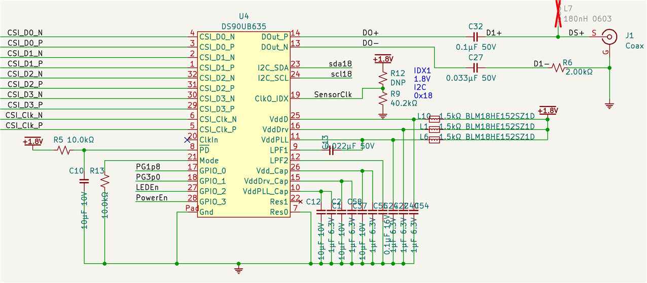
    635 Schematic:

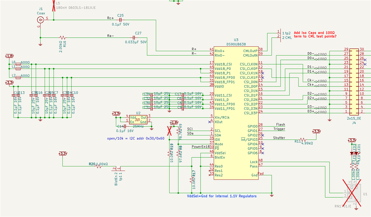
    638 Schematic

    I think the only thing not shown here is the PowerEn18 signal source.  It comes from the power good signal of the 1.8V regulator.  I measured it at 1.5V.

  • Hi Barry,

    Thanks for the update. Is there a reason the 2kOhm termination resistor was selected? We recommend a value of 50Ohms for the termination resistor. 

    Best,

    Zoe

  • Thanks for the thorough review. That resistor sounds like a mistake. We will replace both of them and retest first thing tomorrow. 

  • Hello, Zoe,

    Replacing the termination resistors with the correct value worked!  Imagine that, impedance mismatches are bad.  I looked at that 100 times and even changed the termination capacitor values as a test, but never noticed the resistor value.

    I made a much longer test cable and it is still connecting reliably.  This is a very important project for our small company and seeing these boards connect is a major milestone for us.

    Sorry to drag you into debugging my silly mistake.  I can only say how much I appreciate your help.  My goal as an engineer/person is to come to work and try to help people with their problems.  If your goals are similar you have so succeeded today.

    Please have a great weekend.  Don't hesitate to ask if we can return the favor.

  • Hi Barry, 

    Glad the system is up and running on your end! Please feel free to let us know if there are any remaining questions, happy to help. 

    Best,

    Zoe