This thread has been locked.

If you have a related question, please click the "Ask a related question" button in the top right corner. The newly created question will be automatically linked to this question.

TCAN4550EVM: Unsupported Version 0, while interfacing with Linux board.

Part Number: TCAN4550EVM
Other Parts Discussed in Thread: TCAN4550, TCAN4550-Q1

Hi,

I am trying to interface TCAN4550 to a Linux based processor via SPI. This is my device tree configuration.

&spi1{
   pinctrl-names = "default";
   pinctrl-0 = <&spi1_pins>;
   rtk,spi-for-kernel = <1>;
   rtk,spi-slave-mode = <0>; // SPI master
   rtk,spi-cs-gpios = <&gpioa 2 0>;
   status = "okay";
   tcan4x5x: can@0 {
      compatible = "ti,tcan4x5x";
      reg = <0>;
      #address-cells = <1>;
      #size-cells = <1>;
      spi-max-frequency = <10000000>;
      bosch,mram-cfg = <0x0 0 0 32 0 0 1 1>;
      interrupt-parent = <&gpioa>;
      interrupts = <8 IRQ_TYPE_EDGE_BOTH>;
      device-state-gpios = <&gpioa 1 0>;
      device-wake-gpios = <&gpioa 6 0>;
      reset-gpios = <&gpioa 0 0>;
   };  
};

Once the device boots, I see the following error: 

tcan4x5x spi1.0: Unsupported version number:  0
tcan4x5x spi1.0: TCAN: Probe failed, err=-22

I have referred the following link. But  I did not find any solution on how to set the version number to 3.2.1 or similar. Could someone please help me with this? 

Thanks,

Sai Kiran.

  • Hi Sai,

    You do not set the version number, this is a read-only value returned from the device indicating with version of the MCAN IP is in the device which should be 3.2.1.1.

    If you are unable to read this version register, you may have an error with the SPI drivers not meeting the format required for the TCAN4550.  Do you have the ability to monitor and capture the SPI signals with a logic analyzer or scope?

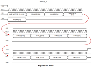
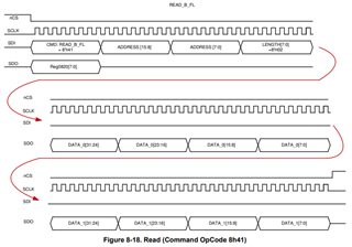
    One common issue is that a single register read or write requires two 32-bit words of data (64-bits total) while the chip select signal is in the low state.  The first word contains the read/write op-code of either 0x41 or 0x61, the register address, and the Length or number of data words for this transaction.  A single register will have the Length = 0x01, but it is possible to work with consecutive registers with a larger Length value and the address is simply the starting address for the consecutive string of registers or memory locations to read or write.

    The second 32-bit (and beyond) is the data to write or be returned from the device on a read. 

    Many SPI drivers break this into separate 32-bit words and pull the chip select signal high in between the words. This will cause a SPI error and the SPI read/write transaction will be terminated.

    Can you verify the SPI signals meet the correct format as outlined in the TCAN4550-Q1 datasheet?

    Regards,

    Jonathan

  • Hi Jonathan,

    Thank you so much for pointing that out. As you have mentioned, I will have a look at the SPI driver implementation and check if the sequence is being broken into separate 32-bit words. Could you please let me know which signals to monitor on the scope, to verify the proper functioning of the device ?

    Thanks,

    Sai Kiran

  • Hi Sai Kiran,

    There are 4 signals in the SPI bus that should be monitored, nCS, SCLK, SDI, SDO.  If you can't look at all 4 signals at the same time, then you could look at the nCS and SCLK to ensure the nCS remains low for the exact number of clock cycles.  There should be 32 clock cycles for the R/W Op-Code, Address and Length fields, and then an additional 32 clock cycles for the number of data words indicated by the Length field.  For a single register read/write there would be a total of 64 SCLK cycles while the nCS signal is low.  However, if the Length field is 2, then there would be an additional 32 SCLK cycles for a total of 96.

    The datasheet shows figures of what the 4 SPI signals should look like with a Length field of 2 that you can reference.

    Regards,

    Jonathan