This thread has been locked.

If you have a related question, please click the "Ask a related question" button in the top right corner. The newly created question will be automatically linked to this question.

TCAN4550-Q1: basic and full tx_object

Part Number: TCAN4550-Q1

Hi,

When we configured the bottom layer (TCAN layer) sending channel, we found that if we send them all to Basic_TxObject, the chip feedback will be busy, so we need to configure the message to be sent to Full_TxObject.
Do you have any reasonable suggestions?
(Which type is configured as basic and what type is configured as full)

Thanks!

  • Hi Mingkang,

    I support the TCAN4550-Q1 at the device level and can help with register configuration and physical layer and pin configuration questions.  I don't know what you are referring to with "Basic_TxObject" and "Full_TxObject" terms because these seem to be associated with some firmware driver that I don't have any experience with.  If you can provide more detailed information about these functions, I can could try to see what the differences are and how they are interacting with the TCAN4550-Q1 at a register level.

    Regards,

    Jonathan

  • How many TCAN 4550 receive and send buffers are there? How to configure multiple cache buffers?

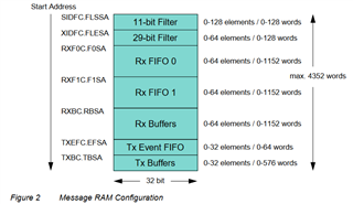
  • The TCAN4550-Q1 contains 2kb of Message RAM (MRAM) that is used for the TX and RX message and Event buffer/FIFO elements as well as the Standard ID (SID) and Extended ID (XID) message filter elements.  You can allocate the MRAM in any way you would like and customize the number of the different types of memory elements for your application.  The different types of elements are optional and for example if you did not want to use the TX Event FIFO, then you do not need to allocate any of the memory for that type of element which allows you more memory for other types of elements.

    The TCAN4550-Q1 uses the MCAN IP developed by Bosch and I would refer you to the MCAN User's Manual for more detailed information about the MCAN features and memory elements. You can find this document at this (Link)

    The following figure can be found in the MCAN User's Manual that provides the maximum number of each element type.

    The MCAN IP will allow you to allocate more elements than the 2kb of MRAM available in the TCAN4550-Q1, so you will need to calculate the memory allocation you want for your application to ensure you do not exceed the 2kb limit.  If you exceed this limit and try to access memory beyond the max address, the TCAN4550-Q1 will automatically wrap back around to the beginning of the MRAM space and you will write or read from an earlier section of the MRAM which can cause errors.

    The TCAN45xx Software User's Guide provides an overview of ow to configure the TX and RX buffer or FIFO elements.  You can find this document at this (Link).

    If you are using the released Linux Driver, the MCAN elements are configured using the "bosch,mram-cfg = <0x0 0 0 32 0 0 0 1>;" command (as an example) and additional details about the order of elements in this command can be found in this (Link).

    Regards,

    Jonathan

  • Is there any other way for TCAN to filter CAN message IDs besides masks

  • The MCAN module has three basic message filter types.

    1.) The Range Filter can be used to accept all received frames with Message IDs in the range defined by the two IDs that you define.

    2.) The Filter element can also be configured for one or two specific Message IDs.

    3.) The Classic Bit Mask Filter is the final type that allows you to set a mask to allow for specific bits in the Message ID to be compared.  If those message bits match, then the message will be accepted.

    Please refer to section 3.4.1 of the M_CAN User's Manual for more information. (Link)

    Regards,

    Jonathan

  • Thank you for your reply, How to configure range filters

  •  The Range Filter can be used to accept all received frames with Message IDs in the range defined by the two IDs that you define.

    Which register should be configured for this operation

    Regards,

    JunWang

  • Hi JunWang,

    Again, please refer to section 3.4.1 of the M_CAN User's Manual for a detailed explanation of the acceptance filtering. (Link)

    You can find an example of how to configure the filters in sections 4.2.3 and 4.2.4 of the TCAN45xx Software User's Guide (Link).

    Filters, including Range Filters, are created by placing a Filter element into the MRAM memory space.  A Standard ID Filter (SIDF) element is 4 bytes (or 32 bits) in length and an Extended ID Filter (XIDF) element is 8 bytes (or 64 bits) in length.  The formatting of these filter elements are defined in section 2.4.5 and 2.4.6 of the M_CAN User's Manual.

    You can have more than one message filter and there can be up to 128 SID and 64 XID filter elements defined.  This allow you to use a combination of different filter types if needed.

    However you will need to allocate a section of the MRAM to hold the Filters you create by calculating the total size of the memory space that is needed for the number of SIDF and XIDF elements you will use. This number and memory start address will need to be written into the Standard ID Filter Configuration (SIDFC) register 0x1084, and the Extended ID Filter Configuration (XIDFC) register 0x1088.

    Note that the filter elements must be placed in consecutive memory cells adjacent to each other (or no gaps in the memory) starting at the start address defined.  Also, if you allocate a filter element, you must actually write a valid filter element into that memory section. This is because when a CAN message is received, the device will start to evaluate that message ID against the first SIDF or XIDF element and see if it passed.  If this message passed such as the message ID was within the range defined by a range filter, then the message will be stored according to the storage location defined in the filter element. However, if the message did not pass the filter, the device will check the message ID against the next filter element you have defined and continue like this until all filters have been verified or the message has passed one of the filter elements.

    If there are gaps, or an invalid filter, there may be errors receiving messages.

    If the RX message does not pass any of the filter elements you have defined then the device will either accept or reject the message according to how you have configured the Global Filter Configuration (GFC) register 0x1080.

    Regards,

    Jonathan