A related question is a question created from another question. When the related question is created, it will be automatically linked to the original question.
If you have a related question, please click the "Ask a related question" button in the top right corner. The newly created question will be automatically linked to this question.
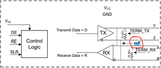
We want to protect the device from transient surge level of 310V/310A in avionics application. Those transient energy if presented at pin A/B/Y/Z Rx/Tx line and would also like to know the internal resistance of pin 15 H/F.
During half duplex the Tx/Rx share the same bus pins (switch is closed). Therefore, we would like to know the current capability of that switch H/_F. Because when the transient is seen on Tx line the switch will see that transient too.
In the datasheet layout section 9.4.1 point 8 talks about adding Transient Blocking Units (TBUs). Where can those be found.
Transient blocking units is a generic term for devices that can clamp voltages. An example of this is a TVS (transient voltage suppression) diode. I personally haven't designed with a GDT (Gas discharge tube) but I have seen these used with TVS diodes in some schematics that required higher level of certification. I would probably start looking at TVS and GDT diodes. I don't believe TI sells either of these so you will likely need to work with another supplier to ensure you select them properly. In addition to this, you can also use some pulse-proof resistors to help limit current during the transient event. You will need to select these based on the expected power dissipation during the event.
We want to protect the device from transient surge level of 310V/310A in avionics application. Those transient energy if presented at pin A/B/Y/Z Rx/Tx line and would also like to know the internal resistance of pin 15 H/F.
You'll need to design clamping devices externally to those pins to make sure they do not exceed the absolute max we spec in the datasheet. For THHD1424 The Y-Z and A-B pins can withstand +/-16V (respect to GND) and if you enable the termination resistor, then you will also need to clamp the differential voltage between Y-Z/A-B to +/-6V. From this perspective, it would be better to have the termination resistor external to the device since it adds an additional weak point. It also seems like you may want to consider a device with higher absolute max voltages to provide more margin of safety. From our portfolio, I would consider the THVD24XX family which allows up to +/-70V fault conditions. Link to the THVD24XX family below.