This thread has been locked.

If you have a related question, please click the "Ask a related question" button in the top right corner. The newly created question will be automatically linked to this question.

TCA6424A: TCA6424A

Part Number: TCA6424A

Hi TI Team,

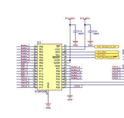
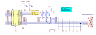
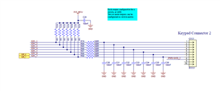
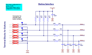
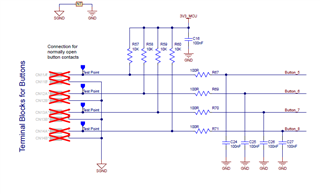
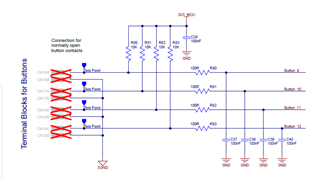
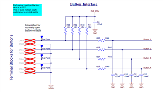
In my design we are using  TCA6424A I/O Expander 24 I2C connected to MCU(STM32F779B), we are not able to read proper input value from external pull up individual port pins, please suggest reference code for reading correct values and also please check below images of schematic for your reference, please review if any corrections required.

Expected result:

Test Case1: If pullup resistor mounted MUC will read HIGH

Test Case2: If pullup resistor unmounted mCU will read LOW

But, above test cases was not pass, please suggest reference code.
  • Hi Prabhu,

    In this specific example, I would expect Test Case1 to PASS and Test Case2 to FAIL. Is this accurate, or are both test cases failing? 

    When an input is left floating on this device, there is no telling what logic state it will be in since this is a high-impedance floating input that can float to whatever voltage it desires. This is especially problematic in systems with high noise such as a motor control near by the floating inputs of the IO expander. You might find that reading the input port registers of this device with floating inputs will yield unpredictable results. 

    Now if both test cases are failing, this means we have a problem with how we are writing and reading from the device. May I have scope captures of the I2C bus to see how the device is being written to / read from? 

    regards,

    Tyler

  • Hi Tyler,

    Thank you very much for your support.

    Test Case1: If pullup resistor mounted MUC will read HIGH then will consider FAIL

    Test Case2: If pullup resistor unmounted MCU will read from IO expander LOW then will consider PASS

    Please check above test case and suggest how to configure resister on MCU( only one bit(individual port )read configuration settings on MCU code.

    Note: I2C expander ports are INPUT  configuration now(please suggest read configuration settings on MCU)

    I have to read only one port(P00) value out of 8 bit or more. How set register settings ?

  • Hi Tyler,

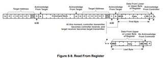
    I have attached I2C scope captures logic analyzer images, please check and let me know any changes required on FW code
    I have to read individual Port pin, please suggest register configuration settings.

    I am not floating any port pins externally pulled HIGH, I have to read same state HIGH individually all port pins.

  • Prabhu,

    Test Case1: If pullup resistor mounted MUC will read HIGH then will consider FAIL

    If pull-up resistors are connected, the MCU will read HIGH logic which fails the case. However, the schematic shows that these pull-up resistors are connected to VCC. I expect the MCU to read HIGH logic on the input port register. Why is this considered a fail case? 

    Test Case2: If pullup resistor unmounted MCU will read from IO expander LOW then will consider PASS

    I expect the input port register to reflect LOW logic state since no pull-up is available. It is most likely that there is some leakage to GND pulling the input pins to a low state. 

    Please check above test case and suggest how to configure resister on MCU( only one bit(individual port )read configuration settings on MCU code.

    Note: I2C expander ports are INPUT  configuration now(please suggest read configuration settings on MCU)

    I have to read only one port(P00) value out of 8 bit or more. How set register settings ?

    TCA6424A powers up with p-ports configured as INPUT's. An i2c read from the device after setting the pointer byte should read the direct data present on the p-port pins. 

    In the scope capture, you send the device address + write bit, then you send 0x01 as the command byte. This will point to input port register 1 and read the contents of this register which are pulled from the parallel data input on the Pxx pins. What logic states are pins 9 - 16 connected to? (P10 - P17)? 

    Regards,

    Tyler

  • Hi Tyler,

    Pins P10-P17 externally pulled up with 10K resistor, please check below image of schematic for your reference.

    If i read port P00 input status, what will be the other ports read configuration settings ?

  • Hi Prabhu,

    When an i2c read occurs on this device, it will read a port at a time. Reading port 0 where the P00 pin is located, it will read the states inside the input port 0 register which will display values on the i2c bus serially P07 - P00. 

    P00 = state of the p-port. When the button on your schematic is idle, P00 = HIGH, when button is depressed, P00 = LOW. 

    If the i2c reads are not reading this correctly, then I believe the next steps is to look at the scope captures of the i2c bus to verify that reads and writes are occurring properly from an analog perspective. The digital flow looks correct from the logic analyzer, but we might be missing some pieces of information from an analog perspective. 

    Are you able to gather o-scope captures of the i2c bus at the TCA6424A?

    Regards,

    Tyler