Hey!
I noticed out EVM has a 10k pulldown REFCLK <-> GND and the typical application has REFCLK tied directly to GND. Which is preferred?
Thanks!
Cameron
This thread has been locked.
If you have a related question, please click the "Ask a related question" button in the top right corner. The newly created question will be automatically linked to this question.
Hey!
I noticed out EVM has a 10k pulldown REFCLK <-> GND and the typical application has REFCLK tied directly to GND. Which is preferred?
Thanks!
Cameron
The 10k pulldown is preferred as this provides an option to use REFCLK if needed.
One other question:
I’ve been trying to chase down an issue where every once in a while the internal PLL stops running, causing the LVDS output clock to drift to a random frequency.
I just wanted to check and make sure there were no errata’s for this part, or that this isn’t a common issue that you all have seen before?
This is most likely due to a jittery DSI clock, if possible would you be able to get your hands on a DSI84 EVM and test it to see if the issue still persists. The EVM has an external REFCLK that provides the DSI84 with a cleaner clock, leading to less PLL drops.
Yeah there are no errata, but If you can send over your register settings, panel spec, and DSI clock frequency I can try verifying the config.
Additionally, try using the DSI Tuner Tool if you haven't already
Ah gotcha, thank you for the insight.
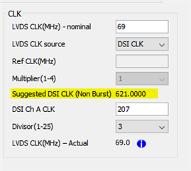
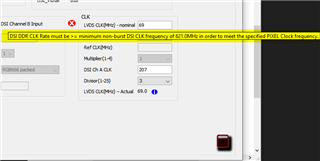
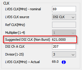
Also, can you tell me more about these notes in the Tuner? Right now we have a 207MHz in, Divisor of 3, 69MHz out. I have not seen this 621MHz requirement before?


Nice catch! Should be 4 DSI lanes. We no longer have the issue after correcting that
Followup question:
Datasheet specifies a 2.175V maximum supply voltage, and long term exposure above that might cause permanent damage.
Hypothetically… do you know what would/could be damaged if the VCC was exposed to 3.3V for extended periods?
Also, if we were in non-burst mode where does this requirement come from? I can’t seem to find it described anywhere else but the DSI tuner.

What would happen if we were running at 207MHz and not 621MHz?
Ah sorry, a bit more guidance would help me out :)
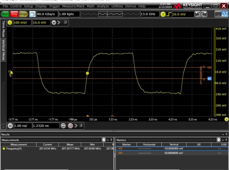
can you please advise on when/why we would want to adjust the equalization registers? I don’t think we have any signal integrity issues that would warrant it (see DSI signal at the bridge attached), but still wanted to get your thoughts?


Datasheet specifies a 2.175V maximum supply voltage, and long term exposure above that might cause permanent damage.
Hypothetically… do you know what would/could be damaged if the VCC was exposed to 3.3V for extended periods?
This may damage the device, I strongly discourage doing this. Why are you looking to use 3.3V?
What would happen if we were running at 207MHz and not 621MHz?
This is just a recommendation and the device should operate fine if the recommended value is not used. As long as the timing spec for the panel/ desired resolution are met there is no issue with using a DSI clock of 207MHz.
can you please advise on when/why we would want to adjust the equalization registers?
The equalization that you want to use will simply apply a positive gain high pass filter across signal. The DSI data rate is not very fast with respect to other protocols such as HDMI and DP, so large dB equalization values are typically not necessary. Here are the registers that adjust the EQ for the clock and data.

There are only 2 settings for EQ on this device, so I would recommend testing both 1dB, 2dB, and no equalization and seeing which waveform has the largest margin in an eye diagram seen at the pins of the DSI84. That would be the ideal EQ value for your system.
. Why are you looking to use 3.3V?
3.3 was used for a few minutes accidentally while evaluating
Ah I see. We haven't done any testing at 3.3V so the device may still be ok, but try to limit further exposure to an out of spec voltage level.