This thread has been locked.
If you have a related question, please click the "Ask a related question" button in the top right corner. The newly created question will be automatically linked to this question.
Hi, Support Team
schematic as below chart: have any concern?
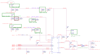
Q1: About TCAN1145A
Q2: about WAKE pin
if any suggestion, Please advise me.
Thanks,
Best regards,
Lawrence
Hi Lawrence,
We are looking into that and will get back to you soon.
Regards,
Sean
Hi Lawrence,
The schematic here looks mostly good. I have a few changes to recommend. See my notes below:
- How to placement termination resistors? Follow EVB termination resistors near transceiver IC or datasheets chapter 13 “Layout” (near connector)?
- About SPI. Is only nINT/SDO need external pull-up 10k ohm (inner open drain)? Other pins can use internal pull-up resistors(~350 k ohm)? (Datasheet Figure 10-5. ;REVISED MARCH 2022)
- About INH pin, need external pull-down 100k ohm for inner PMOS open drain.
I recommend placing termination resistors on the connector-side of the CMC similar to the datasheet recommendation. Note that the EVM is not ideal for layout guidelines as its primary purpose is for accessibility for evaluation and testing. Application layouts may use different techniques to achieve best system results (but will not be as test friendly).
Correct, only the nINT pin has an open-drain configuration which requires an external pull-up. All other SPI signal can be left with no external bias.
The INH pin has an integrated 10M-ohm pull-down resistor. External pull-downs are still recommended to lower the transition time of the signal when the INH pin goes to a high-z state when disabled.
- I only can image, a mechanical if can provide voltage transition will trigger that device wake-up, right?
- The “WAKE” detection “H”(“L”) to “L”(“H”) (VHmin = Vsup-2V, VLmax = Vsup-3.5V) divider from Vsup.
- How to design “WAKE” pins parallel capacitor? Datasheet is 22nF. But EVM is 0.01uF. Which is better
The WAKE circuit on the datasheet is primarily designed for mechanical switches that would have significant debounce requirements and inrush current limiting considerations. For more controlled signal sources, less filtering is needed. If no local wake signal is used, the WAKE pin may be tied to ground for the best power performance in low power mode.
Note that the divider for Vsup is not needed for any device operation, so if no wake source is unused on the local board this pin should be tied to ground.
Let me know if you have any more questions.
Regards,
Eric Schott