This thread has been locked.

If you have a related question, please click the "Ask a related question" button in the top right corner. The newly created question will be automatically linked to this question.

DP83869HM: RGMII to SGMII bridge auto negotiation not succeeding

Part Number: DP83869HM
Other Parts Discussed in Thread: DP83869

Hello,

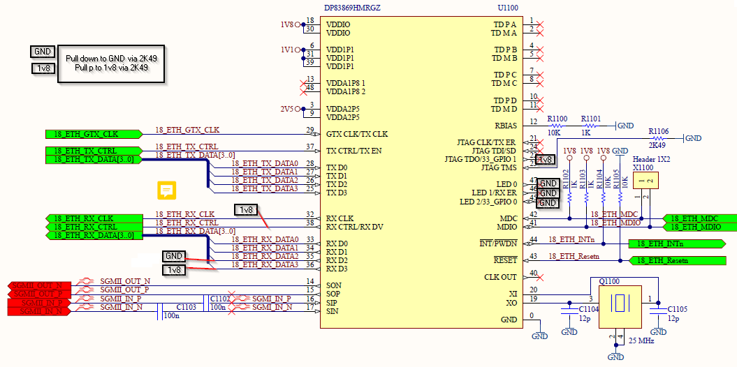
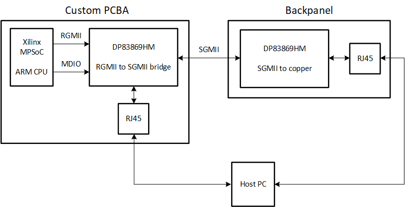
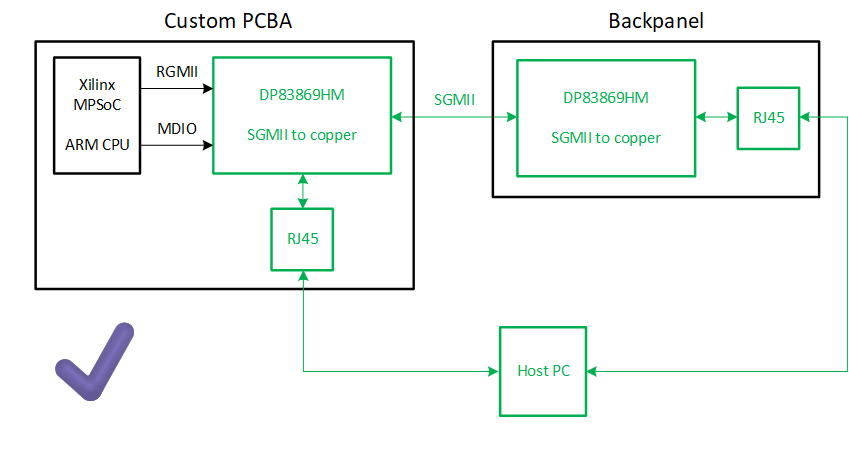
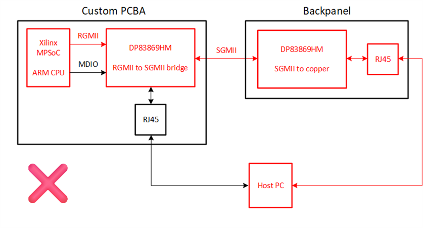
We have a set up with a custom PCBA and a backpanel, both containing an DP83869HM PHY chip. See this block diagram:

┌──────────────────────────────────────────┐     ┌──────────────────────────────┐
│                                          │     │                              │
│ ┌──────────┐      ┌────────────────────┐ │     │ ┌───────────────┐            │
│ │          │RGMII │                    │ │     │ │               │   ┌──────┐ │
│ │  Xilinx  ├─────►│     DP83869HM      │ │SGMII│ │   DP83869HM   │   │      │ │
│ │  MPSoC   │      │                    ├─┼─────┤►│               ├──►│ RJ45 │ │
│ │          │MDIO  │                    │ │     │ │               │   │      │ │
│ │ ARM CPU  ├─────►│RGMII to GMII bridge│ │     │ │SGMII to Copper│   └──────┘ │
│ │          │      │                    │ │     │ │               │            │
│ └──────────┘      └────────────────────┘ │     │ └───────────────┘            │
│               Custom PCBA                │     │           Backpanel          │
└──────────────────────────────────────────┘     └──────────────────────────────┘

The PHY on the custom PCBA is connected to an ARM CPU (which is part of the Xilinx MPSoC) via MDIO and RGMII. The PHY on the backpanel is not connected to the CPU at all, so we cannot access it from the CPU, but it has been confirmed that it is working correctly. The PHY on the custom PCBA has strap resistors to work in RGMII-to-SGMII bridge mode, and the PHY on the backpanel has strap resistors to work in SGMII-to-Copper mode. We are running U-Boot on the CPU to configure the PHY. 

When we try to send a packet from the ARM CPU to a host PC (connected to RJ45), it will only wait for auto negotiation to complete:

ethernet@ff0c0000 Waiting for PHY auto negotiation to complete........

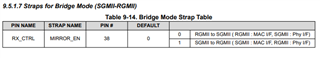
Register 0x1 contains 0x7949, which indicates that auto negotiation has not yet completed. However, we see on the host PC that it has a successful link and it has finished auto negotiation. Register 0x6E contains 0x650, which indicates the boot strap registers have been configured for RGMII-to-SGMII bridge with MIRROR_EN disabled (which is required for the RGMII-to-SGMII bridge, if it was 1, then we would have a SGMII-to-RGMII bridge). However, when we read register 0x1DF, it shows the value 0x43, which has the bit BRIDGE_MODE_RGMII_MAC set to 1, indicating there is a SGMII-to-RGMII bridge. It seems there is a mistake in the datasheet, because section 9.4.8.4 describes we need to write 0x43 to the register to get an RGMII-to-SGMII bridge, but section 9.6.1.65 shows that BRIDGE_MODE_RGMII_MAC (the 4 in 0x43) has to be 0. Nevertheless, both modes are currently not working for us.

In the device driver of the PHY, we have disabled the part where it waits for auto negotiation (this if statement), and then when we set 0x1DF to 0x43, the ARM CPU reports that there is a link and when we disconnect the host PC from the RJ45 connector, it also reports there is no link anymore. However, when it does report that there is a link, we don't see any packets which are sent by the ARM CPU on the host PC. When we set 0x1DF to 0x3, it will only report that there is no link. We tried this because we are not sure if the PHY on the custom PCBA needs auto negotiation, because it seems this is already managed by the PHY on the backpanel.

In all of the described cases, the host PC shows a succesfull link.

Our device tree configurations look the following:

&gem1 {
    phy-mode = "rgmii-id";
    phy-handle = <&phy0>;
    status = "okay";
    mdio: mdio@0 {
        #address-cells = <1>;
        #size-cells = <0>;
        status = "okay";
        reset-gpios = <&gpio 51 GPIO_ACTIVE_LOW>;
        reset-assert-us = <100>;
        reset-deassert-us = <280>;
        phy0: ethernet-phy@05 {
            #phy-cells = <1>;
            status = "okay";
            compatible = "ethernet-phy-ieee802.3-c45";
            reg = <0x05>;
            reset-gpios = <&gpio 51 GPIO_ACTIVE_LOW>;
            reset-assert-us = <100>;
            reset-deassert-us = <280>;
            tx-fifo-depth = <0x1>;
            rx-fifo-depth = <0x1>;
            /* ti,op-mode = <0x03>; */
            ti,max-output-impedance;
            ti,clk-output-sel = <0x01>;
            rx-internal-delay-ps = <2000>;
            tx-internal-delay-ps = <2000>;
        };
    };
};

It seems that we have almost tried everything to get a successful link and auto negotiation, but it does not seem to work. What could we stiill be doing wrong?

Kind regards,
Roy Meijer

  • Hi Roy,

    Thank you for clearly explaining the issue you are seeing, I believe I'm well aligned with the issue at hand.

    Firstly, I want to confirm that the data sheet DOES have a typo. Table 9-14 Bridge Mode Strap Table has the values flipped. This has been corrected in the newest version of the data sheet, which is currently being reviewed for release. Apologies for this headache. Section 9.4.8.4 is also incorrect, Reg 0x1DF = 0x43 is for SGMII-to-RGMII bridge; for RGMII-to-SGMII bridge mode Reg 0x1DF = 0x0003.

    To confirm, the correct strap settings to set the DP83869HM into RGMII-to-SGMII bridge mode is:

    PIN NAME STRAP NAME PIN # PIN STRAP CONNECTION
    JTAG_TDO/GPIO_1 OPMODE_0 22 2.49KΩ Pull-up to VDDIO
    RX_D3 OPMODE_1 36 2.49KΩ Pull-up to VDDIO
    RX_D2 OPMODE_2 35 OPEN
    RX_CTRL MIRROR_EN 38 2.49KΩ Pull-up to VDDIO

    Register 0x6E will tell you what value the PHY was strapped to upon power-up, but this register is not dynamic, meaning a change in OPMODE will not be reflected in this register. Register 0x1DF is dynamic and as you know, can be written to in order to change OPMODEs.

    I understand that you have tried this configuration already due to your correct skepticism with the data sheet, but with this now confirmed, could you try again and let me know how the system behaves? Aside from the incorrect strapping, there might be a few additional issues at hand. 

     Regards,

    Alvaro

  • Hello Alvaro,

    Thank you, we have tried your suggestions. We have put the RX_CTRL strap resistor to a 2.49K pull-up to VDIO. We are seeing that register 0x1DF is set to 0x0003 now as expected. However, it still does not successfully auto negotiate. We have read the value of every register. See the following list:

    Register 0: 0x1140
    Register 1: 0x7949
    Register 2: 0x2000
    Register 3: 0xa0f1
    Register 4: 0x1e1
    Register 5: 0x0
    Register 6: 0x64
    Register 7: 0x2001
    Register 8: 0x0
    Register 9: 0x1300
    Register A: 0x0
    Register D: 0x401f
    Register E: 0x0
    Register F: 0xf000
    Register 10: 0x5c48
    Register 11: 0xa002
    Register 12: 0x0
    Register 13: 0x40
    Register 14: 0x29c7
    Register 15: 0x0
    Register 16: 0x0
    Register 17: 0x40
    Register 18: 0x6150
    Register 19: 0x4444
    Register 1A: 0x2
    Register 1E: 0x12
    Register 1F: 0x0
    Register 25: 0x480
    Register 2C: 0x141f
    Register 2D: 0x0
    Register 2E: 0x221
    Register 31: 0x10b0
    Register 32: 0xd0
    Register 33: 0x0
    Register 37: 0x1
    Register 39: 0x0
    Register 3A: 0x0
    Register 43: 0x7a0
    Register 4F: 0x146
    Register 55: 0x0
    Register 6E: 0x1650
    Register 86: 0x77
    Register 134: 0x1000
    Register 135: 0x0
    Register 170: 0xc0f
    Register 180: 0x752
    Register 181: 0xc850
    Register 182: 0x5326
    Register 183: 0xa01e
    Register 184: 0xe976
    Register 185: 0x19cf
    Register 190: 0x0
    Register 191: 0x0
    Register 192: 0x0
    Register 193: 0x0
    Register 194: 0x0
    Register 195: 0x0
    Register 196: 0x0
    Register 197: 0x0
    Register 198: 0x0
    Register 199: 0x0
    Register 1A4: 0x0
    Register 1A5: 0x0
    Register 1A6: 0x0
    Register 1A7: 0x0
    Register 1DF: 0x3
    Register 1E0: 0x417a
    Register 1EC: 0x1ffd
    Register C00: 0x1140
    Register C01: 0x6179
    Register C02: 0x2000
    Register C03: 0xa0f1
    Register C04: 0x20
    Register C05: 0xd801
    Register C06: 0x9
    Register C07: 0x2001
    Register C08: 0x0
    Register C10: 0x3348
    Register C18: 0x1ff
    Register C19: 0x8


    We have noticed that in register 0x1 (BMSR), bit 2 is low, indicating the link is down. However, register 0x37 (SGMII_AUTO_NEG_STS) has bit 1 is high, indicating that the SGMII auto negotiation has completed. We also notice in register 0xC01 (FX_STS) that bit 2 is low, showing that there is no SGMII link-up or no LP link up. Does this mean there is a successful link between the two PHYs (SGMII), but not a successful link between the PHY on the custom PCBA and the ARM CPU (RGMII)?

    Do you anything else notable from the register values?

    Kind regards,
    Roy Meijer

  • Hi Roy,

    Thank you for the register dump. I didn't get to this until later in the day, please allow me another day to respond.

    Regards,

    Alvaro

  • Hello Alvaro,

    In the mean time, we have tried to measure the RGMII interface. For RX, we measure a clock of 2.5 MHz and for TX, we measure a clock of 125 MHz. We do not see any data on the TX and RX lines. The 2.5 MHz clock on RX also seems an indicator that auto negotiation between the PHY and MAC (on the ARM CPU side) has not been completed yet. Additionally, when we read some of the registers of the MAC, we see that auto negotiation has not been completed and there is no link.

    I hope this information can be useful for you.

    Kind regards,
    Roy Meijer

  • Hi Roy,

    For the sake of keeping us both aligned, I will quickly summarize how the current configuration should work, so that the following debug steps make more sense.

    Xilinx MpSoc <-RGMII-> 869 Bridge <-SGMII-> Ethernet PHY

    When the Ethernet PHY links up, the link capabilities should be communicated to the 869 Bridge via the SGMII interface. Upon receiving the link capabilities, the 869 Bridge will adjust the RGMII clock (125MHz for 1000Mbps, 25MHz for 100Mbps, 2.5MHz for 10Mbps). With no link, the default RGMII clock will be 2.5MHz.

    _____________________________________________________________________________________________________________________________

    Reg 0xC01 in bridge mode tells us the status of the SGMII link, currently it is low. 0xC06[1] gives us another hint, the auto-negotiation between the 869 Bridge and Ethernet PHY was unsuccessful. How are these boards being powered on? It may be that one PHY is "completing" their SGMII auto-negotiation before the other is ready.

    For the 869 Bridge, Reg 0xC0[9] can be used to restart the SGMII auto-negotiation. Reg 0x31[6-5] can be configured to elongate the SGMII Auto-negotiation timer.

    For the Ethernet PHY, unplugging and plugging the ethernet cable back in (and achieving link) will restart the auto-negotiation process.

    Could we give that a shot?

    Regards,

    Alvaro

  • Hello Alvaro,


    Yes your summery is correct, and I want to add to this that both the 869 Bridge and the Ethernet PHY are DP83869 chips. The 869 Bridge is strapped in RGMII-to-SGMII bridge mode and the Ethernet PHY is strapped in SGMII-to-Copper mode. The register dump described in an earlier post is only from the 869 Bridge.

    We managed to add a reset switch to the Ethernet PHY DP83869 chip, and we managed to connect to the MDIO bus of the Ethernet PHY and also dump all registers of the Ethernet PHY. We executed the following steps and dumped the registers after each step:

    1. Boot up the system
    2. Attach ethernet cable
    3. Put Ethernet PHY in reset
    4. Take Ethernet PHY out of reset
    5. Put 869 Bridge in reset
    6. Take 869 Bridge out of reset
    7. Unplug ethernet cable
    8. Attach ethernet cable

    The contents of all registers of the 869 Bridge:

    869 Bridge registers 1. After boot 2. Ethernet cable attached 3. Ethernet PHY in reset 4. Ethernet PHY out of reset 6. 869 Bridge out of reset 7. Eternet cable unplugged 8. Ethernet cable attached
    0x000  0x1140  0x1140  0x1140  0x1140  0x140  0x140  0x140
    0x001  0x7949  0x7949  0x7949  0x7949  0x7949  0x7949  0x7949
    0x002  0x2000  0x2000  0x2000  0x2000  0x2000  0x2000  0x2000
    0x003  0xa0f1  0xa0f1  0xa0f1  0xa0f1  0xa0f1  0xa0f1  0xa0f1
    0x004  0x1e1  0x1e1  0x1e1  0x1e1  0x1e1  0x1e1  0x1e1
    0x005  0x0  0x0  0x0  0x0  0x0  0x0  0x0
    0x006  0x64  0x64  0x64  0x64  0x64  0x64  0x64
    0x007  0x2001  0x2001  0x2001  0x2001  0x2001  0x2001  0x2001
    0x008  0x0  0x0  0x0  0x0  0x0  0x0  0x0
    0x009  0x1300  0x1300  0x1300  0x1300  0x1300  0x1300  0x1300
    0x00a  0x0  0x0  0x0  0x0  0x0  0x0  0x0
    0x00d  0x401f  0x401f  0x401f  0x401f  0x401f  0x401f  0x401f
    0x00e  0x0  0x0  0x0  0x0  0x0  0x0  0x0
    0x00f  0xf000  0xf000  0xf000  0xf000  0xf000  0xf000  0xf000
    0x010  0x5c48  0x5c48  0x5c48  0x5c48  0x5c48  0x5c48  0x5c48
    0x011  0xa302  0xa302  0xa002  0xa302  0xa802  0xa802  0xa802
    0x012  0x0  0x0  0x0  0x0  0x0  0x0  0x0
    0x013  0x40  0x40  0x40  0x40  0x40  0x44  0x44
    0x014  0x29c7  0x29c7  0x29c7  0x29c7  0x29c7  0x29c7  0x29c7
    0x015  0x0  0x0  0x0  0x0  0x0  0x0  0x0
    0x016  0x0  0x0  0x0  0x0  0x0  0x0  0x0
    0x017  0x40  0x40  0x40  0x40  0x40  0x40  0x40
    0x018  0x6150  0x6150  0x6150  0x6150  0x6150  0x6150  0x6150
    0x019  0x4444  0x4444  0x4444  0x4444  0x4444  0x4444  0x4444
    0x01a  0x2  0x2  0x2  0x2  0x2  0x2  0x2
    0x01e  0x12  0x12  0x12  0x12  0x12  0x12  0x12
    0x01f  0x0  0x0  0x0  0x0  0x0  0x0  0x0
    0x025  0x480  0x480  0x480  0x480  0x480  0x480  0x480
    0x02c  0x141f  0x141f  0x141f  0x141f  0x141f  0x141f  0x141f
    0x02d  0x0  0x0  0x0  0x0  0x0  0x0  0x0
    0x02e  0x221  0x221  0x221  0x221  0x221  0x221  0x221
    0x031  0x10b0  0x10b0  0x10b0  0x10b0  0x10b0  0x10b0  0x10b0
    0x032  0xd0  0xd0  0xd0  0xd0  0xd0  0x10d0  0x10d0
    0x033  0x0  0x0  0x0  0x0  0x0  0x0  0x0
    0x037  0x1  0x3  0x0  0x3  0x3  0x3  0x3
    0x039  0x0  0x0  0x0  0x0  0x0  0x0  0x0
    0x03a  0x0  0x0  0x0  0x0  0x0  0x0  0x0
    0x043  0x7a0  0x7a0  0x7a0  0x7a0  0x7a0  0x7a0  0x7a0
    0x04f  0x146  0x146  0x230  0x186  0x156  0x156  0x156
    0x055  0x0  0x0  0x0  0x0  0x0  0x0  0x0
    0x06e  0x1650  0x1650  0x1650  0x1650  0x1650  0x1650  0x1650
    0x086  0x77  0x77  0x77  0x77  0x77  0x77  0x77
    0x134  0x1000  0x1000  0x1000  0x1000  0x1000  0x1000  0x1000
    0x135  0x0  0x0  0x0  0x0  0x0  0x0  0x0
    0x170  0xc0f  0xc0f  0xc0f  0xc0f  0xc0f  0xc0f  0xc0f
    0x180  0x752  0x752  0x752  0x752  0x752  0x752  0x752
    0x181  0xc850  0xc850  0xc850  0xc850  0xc850  0xc850  0xc850
    0x182  0x5326  0x5326  0x5326  0x5326  0x5326  0x5326  0x5326
    0x183  0xa01e  0xa01e  0xa01e  0xa01e  0xa01e  0xa01e  0xa01e
    0x184  0xe976  0xe976  0xe976  0xe976  0xe976  0xe976  0xe976
    0x185  0x19cf  0x19cf  0x19cf  0x19cf  0x19cf  0x19cf  0x19cf
    0x190  0x0  0x0  0x0  0x0  0x0  0x0  0x0
    0x191  0x0  0x0  0x0  0x0  0x0  0x0  0x0
    0x192  0x0  0x0  0x0  0x0  0x0  0x0  0x0
    0x193  0x0  0x0  0x0  0x0  0x0  0x0  0x0
    0x194  0x0  0x0  0x0  0x0  0x0  0x0  0x0
    0x195  0x0  0x0  0x0  0x0  0x0  0x0  0x0
    0x196  0x0  0x0  0x0  0x0  0x0  0x0  0x0
    0x197  0x0  0x0  0x0  0x0  0x0  0x0  0x0
    0x198  0x0  0x0  0x0  0x0  0x0  0x0  0x0
    0x199  0x0  0x0  0x0  0x0  0x0  0x0  0x0
    0x1a4  0x0  0x0  0x0  0x0  0x0  0x0  0x0
    0x1a5  0x0  0x0  0x0  0x0  0x0  0x0  0x0
    0x1a6  0x0  0x0  0x0  0x0  0x0  0x0  0x0
    0x1a7  0x0  0x0  0x0  0x0  0x0  0x0  0x0
    0x1df  0x3  0x3  0x3  0x3  0x3  0x3  0x3
    0x1e0  0x417a  0x417a  0x417a  0x417a  0x417a  0x417a  0x417a
    0x1ec  0x1ffd  0x1ffd  0x1ffd  0x1ffd  0x1ffd  0x1ffd  0x1ffd
    0xc00  0x1140  0x1140  0x1140  0x1140  0x1140  0x1140  0x1140
    0xc01  0x6169  0x6179  0x6159  0x6179  0x6179  0x6179  0x6179
    0xc02  0x2000  0x2000  0x2000  0x2000  0x2000  0x2000  0x2000
    0xc03  0xa0f1  0xa0f1  0xa0f1  0xa0f1  0xa0f1  0xa0f1  0xa0f1
    0xc04  0x20  0x20  0x20  0x20  0x20  0x20  0x20
    0xc05  0x4001  0xd801  0xd801  0xd801  0xd801  0x4001  0xd801
    0xc06  0x1  0xb  0x0  0xb  0xb  0x3  0xb
    0xc07  0x2001  0x2001  0x2001  0x2001  0x2001  0x2001  0x2001
    0xc08  0x0  0x0  0x0  0x0  0x0  0x0  0x0
    0xc10  0x3348  0x3348  0x3348  0x3348  0x3348  0x3348  0x3348
    0xc18  0x1ff  0x1ff  0x1ff  0x1ff  0x1ff  0x1ff  0x1ff
    0xc19  0x0  0x9  0x8  0x9  0x9  0x9  0x9

     
    The contents of all registers of the Ethernet PHY:

    Ethernet PHY registers 1. After boot 2. Ethernet cable attached 4. Ethernet PHY out of reset 5. 869 Bridge in reset 6. 869 Bridge out of reset 7. Ethernet cable unplugged 8. Ethernet cable attached
    0x000  0x1140  0x1140  0x1140  0x1140  0x1140  0x1140  0x1140
    0x001  0x7949  0x796d  0x796d  0x796d  0x796d  0x7949  0x796d
    0x002  0x2000  0x2000  0x2000  0x2000  0x2000  0x2000  0x2000
    0x003  0xa0f3  0xa0f3  0xa0f3  0xa0f3  0xa0f3  0xa0f3  0xa0f3
    0x004  0x01e1  0x01e1  0x01e1  0x01e1  0x01e1  0x01e1  0x01e1
    0x005  0x0000  0xc1e1  0xc1e1  0xc1e1  0xc1e1  0x0000  0xc1e1
    0x006  0x0064  0x006f  0x006f  0x006d  0x006d  0x0064  0x006f
    0x007  0x2001  0x2001  0x2001  0x2001  0x2001  0x2001  0x2001
    0x008  0x0000  0x6801  0x6801  0x6801  0x6801  0x0000  0x6801
    0x009  0x0300  0x0300  0x0300  0x0300  0x0300  0x0300  0x0300
    0x00a  0x0000  0x3c00  0x3c00  0x3c00  0x3c00  0x0000  0x3c00
    0x00d  0x401f  0x401f  0x401f  0x401f  0x401f  0x401f  0x401f
    0x00e  0x0000  0x0000  0x0000  0x0000  0x0000  0x0000  0x0000
    0x00f  0xf000  0xf000  0xf000  0xf000  0xf000  0xf000  0xf000
    0x010  0x5048  0x5048  0x5048  0x5048  0x5048  0x5048  0x5048
    0x011  0x0302  0xbc02  0xbf02  0xaf02  0xaf02  0x0002  0xbc02
    0x012  0x0000  0x0000  0x0000  0x0000  0x0000  0x0000  0x0000
    0x013  0x0040  0x1c40  0x1c40  0x0000  0x0000  0x05c0  0x1c40
    0x014  0x29c7  0x29c7  0x29c7  0x29c7  0x29c7  0x29c7  0x29c7
    0x015  0x0000  0x0000  0x0000  0x0000  0x0000  0x0000  0x0000
    0x016  0x0000  0x0000  0x0000  0x0000  0x0000  0x0000  0x0000
    0x017  0x0040  0x0040  0x0040  0x0040  0x0040  0x0040  0x0040
    0x018  0x6150  0x6150  0x6150  0x6150  0x6150  0x6150  0x6150
    0x019  0x4444  0x4444  0x4444  0x4444  0x4444  0x4444  0x4444
    0x01a  0x0002  0x0002  0x0002  0x0002  0x0002  0x0002  0x0002
    0x01e  0x0012  0x0012  0x0012  0x0012  0x0012  0x0012  0x0012
    0x01f  0x0000  0x0000  0x0000  0x0000  0x0000  0x0000  0x0000
    0x025  0x0480  0x0480  0x0480  0x0480  0x0480  0x0480  0x0480
    0x02c  0x141f  0x141f  0x141f  0x141f  0x141f  0x141f  0x141f
    0x02d  0x0000  0x0000  0x0000  0x0000  0x0000  0x0000  0x0000
    0x02e  0x0221  0x0221  0x0221  0x0221  0x0221  0x0221  0x0221
    0x031  0x10b0  0x10b0  0x10b0  0x10b0  0x10b0  0x10b0  0x10b0
    0x032  0x0050  0x0050  0x0050  0x0050  0x0050  0x0050  0x0050
    0x033  0x0000  0x0000  0x0000  0x0000  0x0000  0x0000  0x0000
    0x037  0x0003  0x0003  0x0003  0x0000  0x0003  0x0003  0x0003
    0x039  0x0000  0x0000  0x0000  0x0000  0x0000  0x0000  0x0000
    0x03a  0x0000  0x0000  0x0000  0x0000  0x0000  0x0000  0x0000
    0x043  0x07a0  0x07a0  0x07a0  0x07a0  0x07a0  0x07a0  0x07a0
    0x04f  0x0156  0x0156  0x0136  0x0220  0x0166  0x0166  0x0166
    0x055  0x0000  0x0110  0x1001  0x1001  0x1001  0x0000  0x0110
    0x06e  0x0c00  0x0c00  0x0c00  0x0c00  0x0c00  0x0c00  0x0c00
    0x086  0x0077  0x0077  0x0077  0x0077  0x0077  0x0077  0x0077
    0x134  0x1000  0x1000  0x1000  0x1000  0x1000  0x1000  0x1000
    0x135  0x0000  0x0000  0x0000  0x0000  0x0000  0x0000  0x0000
    0x170  0x0c0e  0x0c0e  0x0c0e  0x0c0e  0x0c0e  0x0c0e  0x0c0e
    0x180  0x0752  0x0752  0x0752  0x0752  0x0752  0x0752  0x0752
    0x181  0xc850  0xc850  0xc850  0xc850  0xc850  0xc850  0xc850
    0x182  0x5326  0x5326  0x5326  0x5326  0x5326  0x5326  0x5326
    0x183  0xa01e  0xa01e  0xa01e  0xa01e  0xa01e  0xa01e  0xa01e
    0x184  0xe976  0xe976  0xe976  0xe976  0xe976  0xe976  0xe976
    0x185  0x19cf  0x19cf  0x19cf  0x19cf  0x19cf  0x19cf  0x19cf
    0x190  0x0000  0x0000  0x0000  0x0000  0x0000  0x0000  0x0000
    0x191  0x0000  0x0000  0x0000  0x0000  0x0000  0x0000  0x0000
    0x192  0x0000  0x0000  0x0000  0x0000  0x0000  0x0000  0x0000
    0x193  0x0000  0x0000  0x0000  0x0000  0x0000  0x0000  0x0000
    0x194  0x0000  0x0000  0x0000  0x0000  0x0000  0x0000  0x0000
    0x195  0x0000  0x0000  0x0000  0x0000  0x0000  0x0000  0x0000
    0x196  0x0000  0x0000  0x0000  0x0000  0x0000  0x0000  0x0000
    0x197  0x0000  0x0000  0x0000  0x0000  0x0000  0x0000  0x0000
    0x198  0x0000  0x0000  0x0000  0x0000  0x0000  0x0000  0x0000
    0x199  0x0000  0x0000  0x0000  0x0000  0x0000  0x0000  0x0000
    0x1a4  0x0000  0x0000  0x0000  0x0000  0x0000  0x0000  0x0000
    0x1a5  0x0000  0x0000  0x0000  0x0000  0x0000  0x0000  0x0000
    0x1a6  0x0000  0x0000  0x0000  0x0000  0x0000  0x0000  0x0000
    0x1a7  0x0000  0xf020  0xf020  0xf020  0xf020  0x0000  0xf020
    0x1df  0x0046  0x0046  0x0046  0x0046  0x0046  0x0046  0x0046
    0x1e0  0x417a  0x417a  0x417a  0x417a  0x417a  0x417a  0x417a
    0x1ec  0x1ffd  0x1ffd  0x1ffd  0x1ffd  0x1ffd  0x1ffd  0x1ffd
    0xc00  0x1140  0x1140  0x1140  0x1140  0x1140  0x1140  0x1140
    0xc01  0x6169  0x6169  0x6169  0x6149  0x6169  0x6169  0x6169
    0xc02  0x2000  0x2000  0x2000  0x2000  0x2000  0x2000  0x2000
    0xc03  0xa0f3  0xa0f3  0xa0f3  0xa0f3  0xa0f3  0xa0f3  0xa0f3
    0xc04  0x0020  0x0020  0x0020  0x0020  0x0020  0x0020  0x0020
    0xc05  0x4001  0x4001  0x4001  0x4001  0x4001  0x4001  0x4001
    0xc06  0x0003  0x0003  0x0003  0x0000  0x0003  0x0003  0x0003
    0xc07  0x2001  0x2001  0x2001  0x2001  0x2001  0x2001  0x2001
    0xc08  0x0000  0x0000  0x0000  0x0000  0x0000  0x0000  0x0000
    0xc10  0x3348  0x3348  0x3348  0x3348  0x3348  0x3348  0x3348
    0xc18  0x01ff  0x01ff  0x01ff  0x01ff  0x01ff  0x01ff  0x01ff
    0xc19  0x0001  0x0091  0x0011  0x0000  0x0001  0x0031  0x0011

    Do you see anything notable in these register values?

    Next to this, we tried to measure the clock and data alignment of RGMII of the RX and TX data. We did not see anything on the RX data, but we did capture some waveforms from the TX data and clock:

    Channel 2 (blue) is the clock and channel 3 (purple) is the data. The clock does not look correct because we dis not find a good probe for it, but we also tried to measure it with the probe on channel 3 and then it looks like a normal clock signal (square wave). As you can see, the TX data and clock are aligned. Do we have to change anything in our configuration registers for this?

    We also made some changes to the driver so that it will not check for auto negotiation or a link up, and when we execute a DHCP command, we see there is activity on the ethernet cable (the data activity LED blinks), but we don't see any packets received on the host PC connected on the other end of the ethernet cable (we are using Wireshark for this).

    Thank you for your help.


    Kind regards,
    Roy Meijer

  • Hi Roy,

    Thank you for the register dumps. The TX waveforms you scoped are coming from the Xilinx SoC, not our PHY. The fact that you were unable to see any RX_DATA tells us the 869 Bridge is not functioning correctly. 

    Adding the reset switch and register access to the 869 PHY is excellent. In the 869 Bridge register dump, after the bridge is reset Reg 0x0 = 0x140, is this a typo? This would mean that auto-negotiation has been disabled.

    I also want to confirm, in my previous reply I mentioned that the issue might be the SGMII auto-negotiation timing. From your register dump, the DP83869 PHY is linking up, but the SGMII interface between the 869 Bridge and 869 PHY is not being established. This is why you are seeing link and activity on the 869 PHY, but not seeing any received packets. Now that both the bridge and PHY have their own reset switch, can we try releasing both of them from reset at the same time? Please re-read my previous reply for more details.

    Regards,

    Alvaro

  • Hello Alvero,

    Thank you for the quick response.

    The value of 0x140 in register 0 for the 869 bridge is not a typo. It seems it goes into this state every time when do a hard reset from the GPIO pins. Do you have an idea why this is happening? We think it might happen because of the configuration of our strap resistors. Can you check if the strap resistors on the 869 bridge are correct? Here is picture of the schematic:


    We tried to reset both PHY chips at the same time by hand, but without any change. We think it did not help because it seems the window for auto negotiation is at most 11 ms, which is too precise for doing it by hand, and auto negotiation becomes disabled (register 0) when we reset the 869 Bridge. We will add a level shifter between both PHY chips tomorrow so we can reset both at the same time from the console.

    Kind regards,
    Roy Meijer

  • Hi Roy,

    Thanks for confirming the 0x140 value. I don't see anything in your strapping that should cause this. Just for curiosity, can we trying leaving LED[0..2] floating, instead of pulled down to ground?

    I want to keep paying attention to register 0xC01, in RGMII-to-SGMII bridge, this should tell us the link status of the SGMII portion. Can you probe this lines (both the SO[P/N] and SI[P/N]) to see if any signals are being transmitted? This can be done using a differential probe while probing the AC coupling capacitors (C1103 & C1102).

    Regards,

    Alvaro

  • Hello Alvaro,


    We have removed the pull down resistors from LED[0..2], but register 0x0 still contains 0x140 after a hard reset.

    We have now connected both DP83869 to the same reset GPIO pin using a level shifter. We tried to reset both chips at the same time, but this still did not result in a successful auto negotiation. Similar to my previous post, auto negotiation becomes disabled in the 869 bridge after a reset, so we think because of this, it is not possible for auto negotiation to succeed after a reset with the GPIO pin. However, when booting the system, both chips are also reset at the same time by U-Boot and then register 0x0 of the 869 Bridge contains the value 0x1140 (auto negotiation enabled). Do you have an idea why register 0x0 on the 869 Bridge becomes 0x1140 after the reset during boot, but then 0x140 after a hard reset from GPIO?

    We have also tried to configure the 869 Bridge exactly as described in the datasheet (9.4.8.4 RGMII-to-SGMII Bridge Mode) (except that we write 0x3 to register 0x1DF instead of 0x43) with the maximum auto negotiation timer (11 ms, register 0x31 contains 0x10F0), and we have tried to configure the Ethernet PHY exactly as described in the datasheet (9.4.8.1 RGMII-to-Copper Ethernet Modewith the maximum auto negotiation time (11 ms, register 0x31 contains 0x10F0), and then tried to restart auto negotiation for both chips roughly at the same time (possibly not within 11 ms as it involves human error and overhead of the serial interface) by writing 0x1340 to register 0, but this also did not result in a successful auto negotiation.

    Here are the register dumps for both PHY chips after boot up (1), after the GPIO hard reset (2), and after configuring according to the datasheet with the maximum auto negotiation timer and restarting auto negotiation at roughly the same time (3):

    Register 1. 869 Bridge boot up 1. Ethernet PHY  boot up 2. 869 Bridge hard reset 2. Ethernet PHY hard reset 3. 869 Bridge configured 3. Ethernet PHY configured
    0x0  0x1140  0x1140  0x140  0x1140  0x1140  0x1140
    0x1  0x7949  0x796d  0x7949  0x796d  0x7949  0x796d
    0x2  0x2000  0x2000  0x2000  0x2000  0x2000  0x2000
    0x3  0xa0f1  0xa0f3  0xa0f1  0xa0f3  0xa0f1  0xa0f3
    0x4  0x1e1  0x1e1  0x1e1  0x1e1  0x1e1  0x1e1
    0x5  0x0  0xc1e1  0x0  0xc1e1  0x0  0xc1e1
    0x6  0x64  0x6d  0x64  0x6f  0x64  0x6d
    0x7  0x2001  0x2001  0x2001  0x2001  0x2001  0x2001
    0x8  0x0  0x6801  0x0  0x6801  0x0  0x6801
    0x9  0x1300  0x300  0x1300  0x300  0x1300  0xb00
    0xA  0x0  0x3c00  0x0  0x3c00  0x0  0x3c00
    0xD  0x401f  0x401f  0x401f  0x401f  0x401f  0x401f
    0xE  0x0  0x0  0x0  0x0  0x0  0x0
    0xF  0xf000  0xf000  0xf000  0xf000  0xf000  0xf000
    0x10  0x5c48  0x5048  0x5c48  0x5048  0x5c48  0x5048
    0x11  0xa302  0xaf02  0xa802  0xbf02  0xa002  0xaf02
    0x12  0x0  0x0  0x0  0x0  0x0  0x0
    0x13  0x40  0x0  0x40  0x1c40  0x40  0x0
    0x14  0x29c7  0x29c7  0x29c7  0x29c7  0x29c7  0x29c7
    0x15  0x0  0x0  0x0  0x0  0x0  0x0
    0x16  0x0  0x0  0x0  0x0  0x0  0x0
    0x17  0x40  0x40  0x40  0x40  0x40  0x40
    0x18  0x6150  0x6150  0x6150  0x6150  0x6150  0x6150
    0x19  0x4444  0x4444  0x4444  0x4444  0x4444  0x4444
    0x1A  0x2  0x2  0x2  0x2  0x2  0x2
    0x1E  0x12  0x12  0x12  0x12  0x12  0x12
    0x1F  0x0  0x0  0x0  0x0  0x0  0x0
    0x25  0x480  0x480  0x480  0x480  0x480  0x480
    0x2C  0x141f  0x141f  0x141f  0x141f  0x141f  0x141f
    0x2D  0x0  0x0  0x0  0x0  0x0  0x0
    0x2E  0x221  0x221  0x221  0x221  0x221  0x221
    0x31  0x10b0  0x10b0  0x10b0  0x10b0  0x10f0  0x10f0
    0x32  0xd0  0x50  0xd0  0x50  0xd0  0x50
    0x33  0x0  0x0  0x0  0x0  0x0  0x0
    0x37  0x3  0x1  0x3  0x3  0x0  0x0
    0x39  0x0  0x0  0x0  0x0  0x0  0x0
    0x3A  0x0  0x0  0x0  0x0  0x0  0x0
    0x43  0x7a0  0x7a0  0x7a0  0x7a0  0x7a0  0x7a0
    0x4F  0x176  0x116  0x186  0x186  0x186  0x186
    0x55  0x0  0x1001  0x0  0x1001  0x0  0x1001
    0x6E  0x1650  0xc00  0x1650  0xc00  0x1650  0xc00
    0x86  0x77  0x77  0x77  0x77  0x77  0x77
    0x134  0x1000  0x1000  0x1000  0x1000  0x1000  0x1000
    0x135  0x0  0x0  0x0  0x0  0x0  0x0
    0x170  0xc0f  0xc0e  0xc0f  0xc0e  0xc0f  0xc0e
    0x180  0x752  0x752  0x752  0x752  0x752  0x752
    0x181  0xc850  0xc850  0xc850  0xc850  0xc850  0xc850
    0x182  0x5326  0x5326  0x5326  0x5326  0x5326  0x5326
    0x183  0xa01e  0xa01e  0xa01e  0xa01e  0xa01e  0xa01e
    0x184  0xe976  0xe976  0xe976  0xe976  0xe976  0xe976
    0x185  0x19cf  0x19cf  0x19cf  0x19cf  0x19cf  0x19cf
    0x190  0x0  0x0  0x0  0x0  0x0  0x0
    0x191  0x0  0x0  0x0  0x0  0x0  0x0
    0x192  0x0  0x0  0x0  0x0  0x0  0x0
    0x193  0x0  0x0  0x0  0x0  0x0  0x0
    0x194  0x0  0x0  0x0  0x0  0x0  0x0
    0x195  0x0  0x0  0x0  0x0  0x0  0x0
    0x196  0x0  0x0  0x0  0x0  0x0  0x0
    0x197  0x0  0x0  0x0  0x0  0x0  0x0
    0x198  0x0  0x0  0x0  0x0  0x0  0x0
    0x199  0x0  0x0  0x0  0x0  0x0  0x0
    0x1A4  0x0  0x0  0x0  0x0  0x0  0x0
    0x1A5  0x0  0x0  0x0  0x0  0x0  0x0
    0x1A6  0x0  0x0  0x0  0x0  0x0  0x0
    0x1A7  0x0  0xf020  0x0  0xf020  0x0  0xf020
    0x1DF  0x3  0x46  0x3  0x46  0x3  0x46
    0x1E0  0x417a  0x417a  0x417a  0x417a  0x417a  0x417a
    0x1EC  0x1ffd  0x1ffd  0x1ffd  0x1ffd  0x1ffd  0x1ffd
    0xC00  0x1140  0x1140  0x1140  0x1140  0x0  0x1140
    0xC01  0x6179  0x6169  0x6179  0x6169  0x6149  0x6149
    0xC02  0x2000  0x2000  0x2000  0x2000  0x2000  0x2000
    0xC03  0xa0f1  0xa0f3  0xa0f1  0xa0f3  0xa0f1  0xa0f3
    0xC04  0x20  0x20  0x20  0x20  0x20  0x20
    0xC05  0xd801  0x4001  0xd801  0x4001  0xd801  0x0
    0xC06  0xb  0x1  0xb  0x3  0x0  0x0
    0xC07  0x2001  0x2001  0x2001  0x2001  0x2001  0x2001
    0xC08  0x0  0x0  0x0  0x0  0x0  0x0
    0xC10  0x3348  0x3348  0x3348  0x3348  0x3348  0x3348
    0xC18  0x1ff  0x1ff  0x1ff  0x1ff  0x1ff  0x1ff
    0xC19  0x9  0x0  0x9  0x11  0x0  0x0

     
    Do you see anything notable in these register values?

    As for measuring the SGMII lines, we currently do not have differential probe for measuring signals of 1.5 GHz. We will try to measure it later this week and then we will let you know what is the result. In the mean time, we are going to do a loopback test so that we can validate the RGMII interface between the 869 Bridge and the Xilinx MPSoC, and we have soldered an RJ45 connector to the TD_x_A and TX_x_B lines of the 869 Bridge so we can try to find out if it will work in another mode. Do you have any other suggestions for what we can try?

    Kind regards,
    Roy Meijer

  • Hi Roy,

    I believe you are doing an excellent job reworking and debugging this board. The auto-neg disable after a hard reset is very strange. We definitely want to keep auto-negotiation enabled. Please let me know the result of your loopback experiment, I will take a deeper dive into this tomorrow morning.

    Regards,

    Alvaro 

  • Hello Alvaro,

    We were able to measure the SGMII interface. Please find the attached pictures below:

    SGMII RX 1

    SGMII RX 2

    SGMII TX 1

    SGMII TX 2


    Kind regards,
    Roy Meijer

  • Hello Alvaro,

    As I mentioned yesterday, we have also added a RJ45 connector to the TD_x_A and TX_x_B lines of the 869 Bridge. Today we have done some tests with it. We have connected a host PC between the two connector as shown in this block diagram:


    First we have configured the DP83869HM on the Custom PCBA to RGMII-to-copper ethernet mode as described in section 9.4.8.1 of the data sheet. We can now send packets from the Xilinx MPSoC to the Host PC and vice versa. This shows that the RGMII interface between the Xilinx MPSoC and the DP83869HM on the Custom PCBA is working as expected.

    RGMII to copper

    Next, we have configured the DP83869HM on the Custom PCBA to SGMII-to-copper ethernet mode as described in section 9.4.8.7 of the data sheet. We can now send packets from one ethernet port of the Host PC and receive it on the other ethernet port of the Host PC. This shows that the SGMII interface between the DP83869HM on the Custom PCBA and the DP83859HM on the backpanel is working as expected.

    SGMII to copper

    In conclusion, this shows that there is no problem with the RGMII or SGMII interface, and it proves that all our hardware is working as expected, except trhe DP83869HM in RGMII to SGMII bridge mode. In the final product, we need to have an RGMII to SGMII bridge so that we can establish an ethernet connection between the Xilinx MPSoC and the Host PC via the PHY in SGMII to copper on the backpanel. 

    RGMII to SGMII bridge not working

    We were not yet able to try the loopback test, but we also believe this is not necessary anymore, since it has been proven that the RGMII is working as expected. Do you have any other suggestions which we can try to make it work?

    Kind regards,
    Roy Meijer

  • Hi Roy,

    Again, your debugging is excellent. Clearly there is something strange with the DP83869 Bridge mode. Tomorrow I will try using our DP83869HMEVM to check what kind of pulses come out that SGMII portion of the 869 in bridge mode. However, I do not have a way to connect it to another mode to recreate your set up.

    I have seen multiple customers use our 869 in bridge mode and am confident that your set up will work. I found another thread, I didn't notice anything that would help in your situation, aside from further confirmation that we expect Reg 0xC01 of the 869 Bridge to be linked up for proper operation. Please give this a read to see if you catch anything.

    https://e2e.ti.com/support/interface-group/interface/f/interface-forum/1178555/dp83869hm-rgmii-sgmii-bridge-mode-autonegotiation-not-working

    Regards,

    Alvaro

  • Hello Alvaro,

    The bridge is now working. We have set bridge mode to SGMII to RGMII bridge in the OP_MODE_DECODE Register (register 0x1DF, value 0x43), and we have ignored auto negotiation complete in the BMSR Register (register 0x1, bit 5) within the device driver.

    Kind regards,
    Roy Meijer

  • Hello Alvaro,

    Can you please confirm if our solution is correct? Because in one of your previous replays, you described that we have to set 0x1DF to 0x3 for an RGMII to SGMII bridge, but now we have it working with 0x1DF.

    Kind regards,
    Roy Meijer

  • Hi Roy,

    Ever since you solved your own problem, I began working on validating your result. I used the set up below to confirm a few items.

    Smart Bits (data generator) <-Ethernet Cable (1000Mbps)-> DP83867SEVM <-SGMII-> DP83869HMEVM -> Oscilloscope probing the RX_CLK signal.

    When Reg 0x1DF = 0x0043, the RX_CLK freq was 125 MHz (the expected value). You are correct, Reg 0x43 functions as RGMII-to-SGMII bridge. This is very confusing and I apologize for the headache this has caused. This has been noted down to be fixed. 

    Regards,

    Alvaro