This thread has been locked.

If you have a related question, please click the "Ask a related question" button in the top right corner. The newly created question will be automatically linked to this question.

THVD4431: THVD4431- reference schematics

Part Number: THVD4431

Hello,

We are currently in the process of planning for the integration of the THVD4431 component into our industrial gateway project. In this regard, we kindly request reference schematics for the aforementioned part. Additionally, could you please confirm whether the switching between RS232 and RS485 functionalities is software configurable?


Best regards,
Chaithra K S

  • Hi Chaithra,

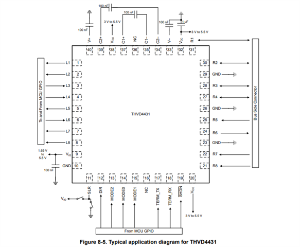
    So the THVD4431 is pretty straightforward when it comes to application schematics using this device - essentially there are logic I/O that are directly connected to MCU GPIO pins and the bus facing pins (R1 - R8) are connected to the external interface connector (DB-9 is pretty common on multi-protocol applications). 

    The THVD4431 has an EVM associated with it as well the THVD4431EVM - that does show an application schematic - I will note that it probably has more components on it than a typical use-case would - I designed the EVM around easy testing so there are a lot of jumpers and additional pads that are generally not necessary for standard applications - however it does largely follow the basic idea of how to use this part in an application. 

    The user guide for the THVD4431EVM is located here: https://www.ti.com/lit/ug/sllu370/sllu370.pdf?ts=1713378539431&ref_url=https%253A%252F%252Fwww.google.com%252F

    In case the schematics are too blurry in the user guide I have also attached the PDF version of the schematic below:

    THVD4431EVM_Sch - Copy.PDF

    This is how the board would come by default if you get one of our THVD4431EVM's from us. 

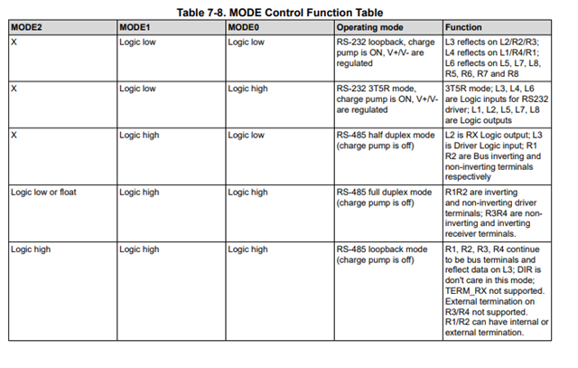
    As for switching between RS-232 and RS-485 mode - it is configurable through software in the controller. What I mean is that there are 3 external pins (MODE0, MODE1, and MODE2)  and depending on the logic level at each MODE pin will determine the final mode of the device.

    So above is the selection chart

    Standard RS-232 is entered by holding MODE1 = L and MODE0 = H where MODE2 is a don't care so it can be left floating/unasserted for standard RS-232.

    Standard Full Duplex RS-485 is entered by holding MODE2 = L or Floating, MODE1 = H, and MODE2 = H.

    Standard Half Duplex RS-485 is entered by holding MODE1 = H, MODE0 = L, MODE2 is a don't care so it can be left floating/unasserted for standard RS-232. 

    The other two modes listed are loopback modes for RS-232 or RS-485. 

    These modes can be changed by the controller operating the device - so at a system level it is software configurable. 

    Please let me know if you have any other questions and I will see what I can do - and if you want us to take a look at the schematic to check for problems we would be more than happy to assist you with that. 

    Best,

    Parker Dodson