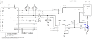
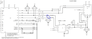
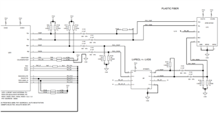
Part Number: DP83822IF
Other Parts Discussed in Thread: DP83822EVM
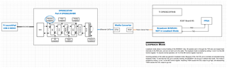
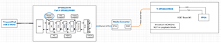
I've been trying to get the DP83822IF talking with Broadcom 5241. Was working with Evan from TI but my existing thread is now locked.
Original question:

Part Number: DP83822IF
Other Parts Discussed in Thread: DP83822EVM
I've been trying to get the DP83822IF talking with Broadcom 5241. Was working with Evan from TI but my existing thread is now locked.