This thread has been locked.

If you have a related question, please click the "Ask a related question" button in the top right corner. The newly created question will be automatically linked to this question.

HD3SS3212: IBIS or S-Parameter

Part Number: HD3SS3212
Other Parts Discussed in Thread: TUSB522P, HD3SS3220, TMUXHS4212, TUSB322

HI ,

Can you please provide the IBIS Model of HD3SS3212 for Hyperlynx Simulation? 

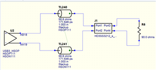
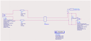
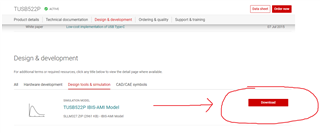
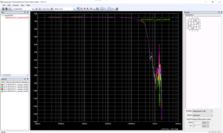
I have downloaded S-Parameter file from TI Website. How to select the ports for A1+/- to C1+/- pins of the MUX, I have selected A1+ as port1, C1+ as port3, A1- as port2 and C1- as port 4, Is this the right way of connecting?

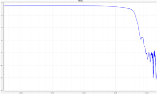
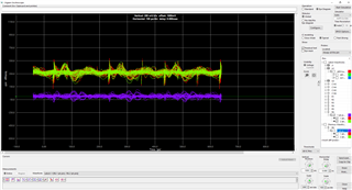
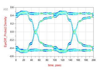
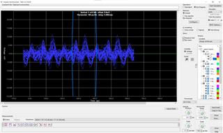
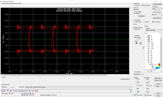
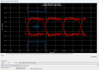
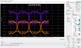
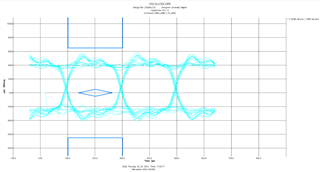
But still my waveform is not good.

If you provide the IBIS Model that will be more Helpful.

BR,

Rajesh G

  • Hi Rajesh,

    Can you please provide the IBIS Model of HD3SS3212 for Hyperlynx Simulation? 

    We do not have an IBIS Model for this device. We typically use S-parameters to simulate our MUX device performance.

    I setup the S-parameter myself, and you have the correct port configuration (port1/2 = A+/-, port 3/4 = C+/-). Which waveform are you looking at in particular?

    For example, this waveform S [4,2] shows the insertion loss between C- and A-. Is this the waveform you're referring to?

    Best,

    Shane

  • HI Shane,

    Thanks for your reply,

    Yes, the Insertion loss you have shown is the one I am referring too.

    And I use the same ports for LineSim in Hyperlynx, my USB waveforms doesn't seem to be good as below.

    Can you please help me on this? And more over If I use only the driver without MUX my waveform is within the USB Eye pattern.

    BR,

    Rajesh G

  • Hi Rajesh,

    Are you using Keysight ADS to simulate your system?

    If so, can you please archive the simulation setup and send me the file? I want to see if there's any issue with the implementation of our MUX in the simulation.

    If you'd like to share this privately, you can accept my friendship request and direct message me the file over E2E.

    Best,

    Shane

  • Hi Shane,

    I am not using Keysight ADS to simulate, I am using Hyperlynx SI/PI tool for simulating Line and Boardsim for my PCB Design.

    BR,

    Rajesh G

  • Hi Rajesh,

    Thank you for your patience. I re-created your setup in Keysight ADS to try and reproduce the issue:

    When I run the simulation, I get the following Eye diagram:

    The eye diagram I saw on ADS looks better then the one you have. We only use ADS for simulations, so I'm not sure whether Hyperlynx is interfering with the s-parameter file in some way.

    Just to confirm, does the simulation setup I made accurately reflect your system?

    Best,

    Shane

  • Hi Shane,

    Thanks for updating with simulation results, You are correct your setup reflect exact my setup. No difference.

    Can you please share the RX_Generic.ibs model for USB, I will try to use and simulate the results?

    BR,

    Rajesh G

  • Hi Rajesh,

    Here's the .ibs mode for that part:

    RX_generic.ibs

    I based my simulation on the IBIS model for the TUSB522P. This model includes the RX_generic.ibs and TX_generic.ibs files.

    I hope this helps, let me know if you have any questions.

    Best,

    Shane

  • Thank you Shane, 

    Let me run the simulation and provide you the update on the s-parameters.

    BR,

    Rajesh G.

  • Thanks Rajesh,

    I'll keep this thread open for any updates.

  • Hi Shane,

    I tried your configuration in Hyperlynx, but I couldn't see the results.

    If I run the S-Parameters in Hyperlynx touchstone these are the below results:

    If I use the same as above touchstone configuration below are the results:

    If run without HD3SS MUX, just simulating only the driver, below is the result:

    Can you please help me on this issue?

    BR,

    Rajesh

  • Hi Rajesh,

    Let me see if I can get Hyperlynx and re-produce the issue. I'll aim to have an update early next week.

    Best,

    Shane

  • Hi Rajesh,

    I haven't been able to get Hyperlynx myself, but I have a couple questions to get a better idea of this issue.

    1. Are you able to run this simulation with any other MUX S-parameters on Ti.com? Here are a couple you can try:

    - HD3SS3220: https://e2e.ti.com/cfs-file/__key/communityserver-discussions-components-files/138/HD3SS3220_2D00_TX_2D00_to_2D00_TX2.s4p ReadMe: 

    This is s-parameter models for through path. This provides model for an average HD3SS3220 ON channel. This can be used for Insertion and Return Loss simulations.
    
    The port order of this s4p file is as follows.
    [1 <--> 2]
    [3 <--> 4]
    
    (1 3) is input pair and (2 4) is output pair.


    - TMUXHS4212: https://e2e.ti.com/cfs-file/__key/communityserver-discussions-components-files/138/TMUXHS4212.s4p ReadMe: 

    This is s-parameter model for through path. This provides model for an average TMUXHS4212 ON channel. This can be used for Insertion and Return Loss simulations.
    
    Differential Port 1 between single ended PORTS 1 and 3 of the model
    Differential Port 2 between single ended PORTS 2 and 4 of the model


    2. Have you tried changing the port configuration? 

    - You seem to have the correct configuration, but it may be a good idea to try other port settings to see if one works.

    Best,

    Shane

  • Hi Shane,

    Sorry for the late reply, I was on Long Leave.

    Let me try the other s-parameters in the simulation and update you on the results.

    BR,

    Rajesh G

  • Thanks Rajesh,

    I'll leave this thread open for any updates. 

    Best,

    Shane

  • Hi Shane,

    I have tried to simulate the HD3SS3220: HD3SS3220-TX-to-TX2.s4p s-parameter fine, I am able to see the results without any issue as below.

    Can you please let me know how to simulate with HD3SS3212 s-parameter file.

    And why do we need to have ground clearance under the MUX Pins?

    BR,

    Rajesh G

  • Hi Rajesh:

       Shane is out  of office for two weeks, I will help to support this issue.

        Do you mean you can simulate with HD3SS3220 S4P file, but have issue with HD33SS3212? actually it's the same mux for this two devices.

        For  ground clearance under the MUX Pins, since there mismatch for pin pad width and trace width, the ground clearance or void is to minimize the discontinuities between the pad and trace.

    Regards

    Brian

  • Hi Brian,

    Thanks for your reply,

    But I have tried all the possible combinations for port configuration with HD33SS3212, still I am unable to the signal out of the S-Parameter file. When I try with HD3SS3220 S4P file, I got the waveform as mentioned above.

    Can you help me with latest S-Parameter file for HD33SS3212, As I need to document the simulation results with exact part s-parameter only to validate the signal.

    BR, 

    Rajesh G

  • And what is the Inner length (Substrate Length) of the MUX from A to B and A to C? This will help in doing the length matching in my PCB Layout.

  • Hi Spinidhi:

               This is the model for the S4P data from TI.com: insertion loss is S13 and S24, but data didn't seems match to the datasheet spec.

       I talked to our validation engineer and I was told this S4P model was took by our 20Ghz VNA and this VNA don't have good de-embedding performance.

      We may need to re-take it with 50Ghz VNA.

      Regarding length matching, the difference between Substrate Length inside the chip can be neglected , we never heard any length matching issue for this device.

    Regards

    Brian

  • Hi Spinidhi::

       please accept my friendship request so I can send new S4P model to you.

    Regards

    Brian

  • HI Brian,

    Thanks for your response,

    Accepted your request.

    BR,

    Rajesh.

  • Please check  your message box for S4P model.

    Regards

    brian

  • Hi Brian,

    If I simulate the USB below is how the simulation result look like on either pin of the differential pair, 

    Signal is either above origin or below origin. Can you please help me in correcting this. 

    I am using AC Coupling Capacitors in series.

    BR,

    Rajesh G.

  • Did you get right port?

    port 1 and 3 is differential port 1, port 2 and 4 is differential port2.

    Regards

    brian

  • Yes, I got the right port, EYE opening is looking good, but the offset is what we need to figure out. The above wave form is differential only, but at 2 pins of diff pair

    BR,

    Rajesh G.

  • It seems you got correct  simulation result with HD3SS3220, are there any difference for simulation setup with HD3SS3212?

    Actually  HD3SS3220 is  HD3SS3212 + TUSB322

    Best

     brian

  • If I am using AC Coupling Capacitor, I am seeing the shift in the DC bias point, how to correct that Shift?

    In the Above simulation results you can see 1 diff pair simulations at 2 points, there is offset to either positive or negative side. How to correct that?

    BR,

    Rajesh G.

  • it seems like single ended P and N signal.  Differential  output should be just one signal.

    Did you compare  with HD3SS3220?

    Regards

    brian

  • Hi Brain,

    I have found a solution, I need to enable a setting in Hyperlynx to settle the AC Coupling Capacitors connected in series before simulations.

    Below is the waveform of my design:

    BR,

    Rajesh G

  • Glad it works, why it didn't  crossed at 0v?

    Best

    brian

  • There is some offset, working on it to solve. Will get back to you if any help required.

  • ok,  I will close this ticket and you can reopen  if needed. Also please  press the Resolved button.

    Best

    Brian

  • Hi Brian,

    In HD3SS3212 datasheet, the intra pair skew mentioned is 6ps, is this equivalent to 6ps/inch or 6ps/meter? As per the USB Standards the Skew is 15ps/m.

    Is this skew added both HD3SS3220 and HD3SS3212 IC S-Parameter file?

    If not can you provide the updated one with skew details?

    BR,

    RAJESH G

  • Hi

             Skew data is absolute data  in ps, 

    S-parameter should include  skew data. Please see attached example .

    Look at column C for the calculation. Group delay is phase delta/freq. delta, you need to watch the units, in this example phase is in degree.

    group-delay-example.xlsx

    Best

    Brian


  • Is HD3SS3212 Compliant for USB Standards for USB Qualification?

    BR,

    Rajesh G

  • yes, It's been used in many USB3 Gen2 projects.

    Best

    Brian