This thread has been locked.

If you have a related question, please click the "Ask a related question" button in the top right corner. The newly created question will be automatically linked to this question.

TUSB1142: USB3 driver

Part Number: TUSB1142
Other Parts Discussed in Thread: TUSB321, , TPS2000E, TPS2001E, TPS2556, TPS2557, TUSB320

Hello. As described in a previous post I have to design a board to drive and USB from an USB3 type-C connector to another USB3 connector at a distance of about 0.6m/2ft.

Everything is powered by the HOST DFP port. I don't need to provide power to the device, I need only the data connection. 

Here my project choices:

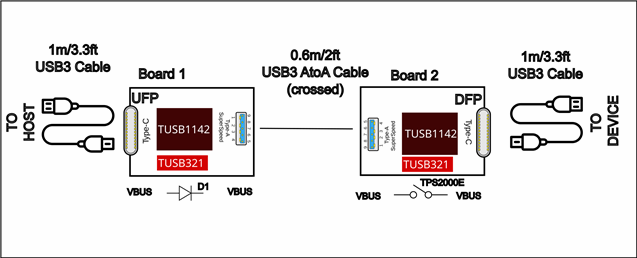
1. I planned to use TUSB1142 as driver and 2:1 and 1:2 mux.  The DIR output of the TUSB321 drives the TUSB1142 FLIP input.

2. On board2 the UFP connector should be a type-B but, in order to have a single board, I put a type A since non standard A to A cables (crossed) are available on the market.

3. TUSB321 is used in dual role port mode (DRP). 

4. Once TUSB321 has detected the port role and set the DIR and ID (max 133ms), the TUSB1142 EN pin rises, delayed by 400ms by the TLV802EF and the pin straps are acquired.

I would check if this management of the VBUS voltage is acceptable:

Board1:

- VBUS is driven directly from the type-C connector to the type-A connector through a Diode (Vf=250mV).

Board2:

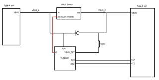
- VBUS on the DFP Type-C connector is enabled by the TPS2000E switch driven by the ID pin of the TUSB321.

- The cable on the right side which connects the DFP to the device should be connected after the TUSB321 and  the TUSB1142 EN pin is asserted.

Another question I have regards the FLIP input on the TUSB1142: it should not be latched with the EN pin and should change when a cable is inserted after the EN is asserted: is it correct?

Attached the schematic  USB3DRV2.pdf

Thank you.

  • Hi Mario,

    I have a couple questions about your design to get a better idea:

    1. Is the schematic you sent for Board 1 or Board 2? I see there is both a TPS2000E switch (from board 2) and the diode D1 (from board 1) in this schematic. So I'm not sure which side I am looking at

    3. TUSB321 is used in dual role port mode (DRP). 

    2. Which board uses the TUSB321 as a DRP? You need to control the VBUS on a DRP so it would not work with the diode from board 1.

    - VBUS is driven directly from the type-C connector to the type-A connector through a Diode (Vf=250mV).

    3. A USB-A VBUS is typically limited to 5V/900mA, while USB-C can go up to 5V/3A with our 321. What amount of current do you plan to pass over the USB-A cable?

    Best,

    Shane

  • Hi Shane. 

    Thank you for the quick answer. Sorry for my approximate explanation in my previous message. 

    1.

    1. Is the schematic you sent for Board 1 or Board 2? I see there is both a TPS2000E switch (from board 2) and the diode D1 (from board 1) in this schematic. So I'm not sure which side I am looking at

    The idea is to use two identical boards on the left (Board1) and right side (Board2), if possible.

    For this reason I used a USB type-A connector also on the right side (Board2) where the type-B connector should be used. 

    Board1: 

    Type-C connector acts as UFP 

    Type-A connector acts as Downstream

    5V are connected from type-C to type-A though diode D1.

    Board2: 

    Type-A connector acts as Upstream.

    Type-C connector acts as DFP 

    5V are connected from type-A to type-C though TPS2000E which is enabled by the ID signal from TUSB321.

    2.

    Which board uses the TUSB321 as a DRP? You need to control the VBUS on a DRP so it would not work with the diode from board 1.

    The idea was to use TUSB321 as DRP so that in board1 it acts like UFP while in board2 it works as DFP. 

    It is not clear to me how to control the VBUS in UFP (Board1). Could I use the inverted ID signal (or mount the active hight TPS2001E ) to enable the VBUS toward the downstream port? 

    On the right side (Board2), is it correct to enable the downstream VBUS with the switch controlled by the TUSB321 ID signal?

    3.

    3. A USB-A VBUS is typically limited to 5V/900mA, while USB-C can go up to 5V/3A with our 321. What amount of current do you plan to pass over the USB-A cable?

    Here I planned to limit to 5V/900mA but if I could reach 1.5A or 3A it will be a plus. The cable I plan to use is rated to 3A. The TPS2xxE maximum current is 2A but it could be replaced by TPS2556 and TPS2557 which are rated for 5A. 

    In the case the development of a single board for the right (board-A) and left (board-B) sides becomes problematic, I would like to have the same PCB, with different BOM. 

    In this case I don't need to set the TUSB321 in DRP mode and the mode will be set by the PORT configuration strap.

    Thank you for your support!!!

  • Hi Mario,

    It seems like this application is similar to our TUSB320 EVM. That EVM can operate as either a DFP or UFP and may be a good reference for the TUSB321 in your design.

    Could I use the inverted ID signal (or mount the active hight TPS2001E ) to enable the VBUS toward the downstream port? 

    The ID signal from the TUSB321 is active low. When ID is pulled low, we want the VBUS switch to enable and provide power on the Type-C port. Here is a good resource for how to control VBUS with the ID pin from the 321.

    • If your VBUS switch is active-high, you can invert the ID signal to control it. It is simpler to use an active-low VBUS switch because you can direct connect ID to the EN pin
    On the right side (Board2), is it correct to enable the downstream VBUS with the switch controlled by the TUSB321 ID signal?

    You are correct. You need to use a VBUS switch on this port that is controlled by the ID signal from the CC controller because it can act as a DFP or DRP. 

    I drew a diagram for the VBUS path based on your schematic. This implementation would be ok to support either DFP or UFP mode 

    I have one question on this. Will you only use power from the type-A port when the board is in DFP mode?

    You have the 321 configured to provide default current (900mA) on the type-C port when it is a DFP. If you are only pulling 900mA from the type-A port to power the board, you wouldn't have enough current to supply the Type-C DFP with 900mA because the 1142 and 321 will draw some of this power.

    The TUSB1142 is implemented ok, but I don't see any ESD protection on the SuperSpeed lines. I recommend using a diode like the PUSB3FR4 to protect the 1142 from ESD strikes.

    Best,

    Shane

  • Thank you for your precious support Shane, 

       the TUSB320 EVM is very similar to the solution I am developing. I am studying it in details. 

    I have one question on this. Will you only use power from the type-A port when the board is in DFP mode?

    Yes the "Board2" on the right connects to devices and should take power from its left path.

    You have the 321 configured to provide default current (900mA) on the type-C port when it is a DFP. If you are only pulling 900mA from the type-A port to power the board, you wouldn't have enough current to supply the Type-C DFP with 900mA because the 1142 and 321 will draw some of this power.

    Right, I have to increase the current settings. The host source is known and we have power availability on that side. 

    The TUSB1142 is implemented ok, but I don't see any ESD protection on the SuperSpeed lines. I recommend using a diode like the PUSB3FR4 to protect the 1142 from ESD strikes.

    Correct, yesterday I put the PUSB3FR4 as in the TUSB1142-EVM. I noticed,on the EVMs, there are not ESD protections on the USB2 D+,D- signals. 

    I would thank you for your support, please let me keep this thread open for a while, in the next days I will try to close the design.

  • Sounds good. I'll leave this thread open for any updates.

    Best,

    Shane