This thread has been locked.

If you have a related question, please click the "Ask a related question" button in the top right corner. The newly created question will be automatically linked to this question.

TUSB1142: USB redriving design principle

Part Number: TUSB1142
Other Parts Discussed in Thread: TPS25820, TUSB1044, TUSB321, TUSB322

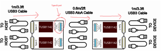
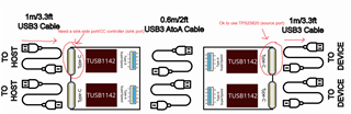
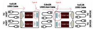
Hello, I have to implement a board which takes USB3 from a host into a USB3 type-C connector and drive in some way the USB3 signal towards another type-C connector. 

I have planned to use the TUSB1142 as shown in the attached picture. Design specs requires USB3.1 even if TUSB1142 supports USB3.2.

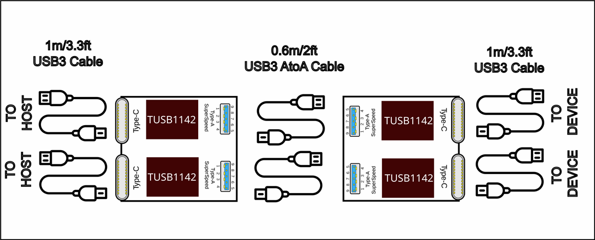
There are two ports to connect but these are separate and we could consider only the first row since the second row is a copy of the first. The USB-A to USB-A  cable in the middle crosses the TX and RX lines.

I plan to power the TUSB1142 from the VBUS using a 3V3 LDO. With 2 diodes I could take the power from the VBUS of the Type-C connector or from the VBUS of the Type-A connector.

I also plan to use the TPS25820 as in the EVM as USB CC/PD controller.

I would ask if this solution could work. 

Thank you.

  • Hi,

    Instead using TUSB1142, why not use TUSB1044, https://www.ti.com/lit/ds/symlink/tusb1044.pdf for this particular design?

    Thanks

    David

  • Thank you for your reply David, 

         I chose the TUSB1142, since it integrates the MUX and I have only to wire only one TX, RX pair (plus USB2 DP DN) and this provide also a solution for the CC1, CC2 lines.

    My goal is to connect USB-C ports from one side to the other.

    Looking at the TUSB1044 it is not so clear to me how to do this. 

    My doubt is the management of the VBUS since I don't have an external power supplier and I need to use the voltage provided by the VBUS in the type-C connector: in this case the USB-C on the left receives power from the host while the USB-C on the right sink power to the device.  

  • Hi Mario,

    I believe this design could work, but there are a few things I want to point out:

    1. The USB cable in the middle should not be a type-A to type-A cable. USB cables take the power/data source from a USB-B port to a USB-A port, so you may want to change your diagram to account for this

    2. The TPS25820 is a source only controller. This means it is ok to use on your right-side type-C port (source), but would not work for the left side type-C port (sink). You could use a simple CC controller for the left side port to determine attachment and orientation. Consider using the TUSB321 or TUSB322 for this purpose:

    3. If you're using only the VBUS from the left USB-C connector, you need to make sure it passes enough power to supply two TUSB1142s, a TPS25820, the connected downstream device, and whatever CC/port controller you use on the sink side port. Keep in mind that this may limit the power on the downstream (right) type-C port.

    I hope this helps, let me know if you have any questions.

    Best,

    Shane

  • Hi Mario,

    I made a mistake in my last reply. For number 1, I swapped the USB-B and USB-A positions in my answer. USB cables take power/data from a USB-A port to a USB-B port. 

    Best,

    Shane

  • Thank you very much for your detailed answer, Shane. 

    Yes, the correct cable should be Type-B to Type-A but this connection is internal to our box and I would design a single board for the two sides. For this reason I planned to use a non-standard cable which is however available on the market. From an electrical point of view the signal should be the same (the cable crosses the TX and RX pairs). 

    I will try to develop a single PCB with the possibility to mount the TPS25820 (source) or TUSB32x (sink).

    In the next days I will start with the design, thank you again.

    mario