Because of the Thanksgiving holiday in the U.S., TI E2E™ design support forum responses may be delayed from November 25 through December 2. Thank you for your patience.

This thread has been locked.

If you have a related question, please click the "Ask a related question" button in the top right corner. The newly created question will be automatically linked to this question.

DS90UB962-Q1: We can't get the video from UB962

Part Number: DS90UB962-Q1

Hi FPD Link Team,

My customer are designing AVM system and set UB933 for output, and IVI receiver is UB962. Besides, the IVI system has been RTM couldn't make change any more.

Here is UB962 Raw 10 8-bit register configure:

Camera Configuration.zip

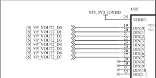
Here is the UB933 schematic:

DS90UB933TRTVRQ1_2_Reviewed_20240229.pdf

I think this is the main reason why we couldn't get the video: UB933 uses lower 8bit and UB962 is set to high 8bit model.

We wonder if you have any other ways to make the video normal except changing the schematic and UB962 0x7C, thanks.

Best Regards,

Jack

  • Hello Jack,

    For getting the attached register dump, how many cameras were connected to the UB962? to which RX port?

    From the provided dumps, it looks like only RX port0 has LOCK high. But CSI TX ports are disabled (see reg 0x33) and port forwarding is also disabled (see reg 0x20)!

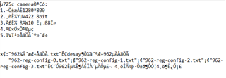
    Can you translate what is written in the "readme" file?

  • Hi Hamzeh,

    I get a camera using UB933 for test and we get the normal video, the difference is that this module uses DIN2~DIN9. So we do suspect this is the main reason. After all, IVI is set use UB962 Raw 10  using upper 8 bits:

    I wonder if we could change UB962 registers via UB933, if yes please tell us how to set UB962 0x7C register to 0XE0

    ADAS SOC--------UB933----------UB962---------IVI

    Best Regards,

    Jack

  • Hi Jack,

    If you have LOCK then you should have forward channel I2C communication. You need to enable I2C pass-through on the UB933 reg 0x03[2] and make sure you have the correct DES ID and Alias in reg 0x06 and 0x07, after that you can access the DES and change reg 0x7C. 

  • Hi Hamzeh,

    Could you please tell me how to set it in software, thanks!

    0X03=0XC5

    0X06=

    0X07=

    0X7C=

    Best Regards,

    Jack

  • Hello Jack,

    0X06 = I do not know the value, this depends on your design/ use case.

    0X07=I do not know the value, this depends on your design/ use case.

    0X7C[7:6] =  If you need upper 8-bits write 10, if lower 8-bits write 11

  • Hi Hamzeh,

    Thanks for your reply!

    My customer still couldn't get video when connecting the IVI system using UB962:

    ADAS SOC--------UB933----------UB962 (IVI board)   #couldn't get the video

    But they get the normal video with a test board also using UB962

    ADAS SOC--------UB933----------UB962 (test board)  #get the normal video

    Here are the registers, please help to have check and analyze it, thanks!

    Test board with 960 (get the normal video).txt
    # i2cdump -y 3 0x10
         0  1  2  3  4  5  6  7  8  9  a  b  c  d  e  f    0123456789abcdef
    00: 60 00 1e 40 d0 01 00 fe 1c 10 7a 7a 0f b9 71 ff    `.?@??.???zz??q.
    10: 01 05 09 00 0d 00 00 00 01 0d 05 75 30 00 04 05    ???.?...???u0.??
    20: 00 03 00 00 00 00 00 00 00 00 00 00 00 00 00 00    .?..............
    30: 00 00 00 63 00 01 00 01 00 00 00 00 00 00 00 00    ...c.?.?........
    40: 00 a9 71 01 00 00 20 00 00 00 00 12 01 03 cd 23    .?q?.. ....????#
    50: 80 00 00 00 00 00 00 00 58 00 00 ba b0 30 00 00    ?.......X..??0..
    60: 00 00 00 00 00 00 00 00 00 00 00 00 00 7f a8 88    .............???
    70: 1e 2c e4 03 20 0a 00 c5 00 01 0f ff c0 00 00 00    ?,?? ?.?.??.?...
    80: 00 00 00 00 00 00 00 00 00 00 00 00 00 00 00 00    ................
    90: 10 f6 00 00 ff ff 00 00 00 00 00 00 00 00 00 00    ??..............
    a0: 00 00 00 00 00 1c 00 00 00 00 00 00 00 00 00 00    .....?..........
    b0: 1c 3a 15 08 25 00 18 00 88 33 83 74 80 00 00 00    ?:??%.?.?3?t?...
    c0: 00 00 00 00 00 00 00 00 00 00 00 00 00 00 00 00    ................
    d0: 00 43 94 17 60 f2 00 03 00 00 00 00 00 00 00 00    .C??`?.?........
    e0: 00 00 00 00 00 00 00 00 00 00 00 00 00 00 00 00    ................
    f0: 5f 55 42 39 36 30 00 00 00 00 00 00 00 00 00 00    _UB960..........

    IVI board with 960 (couldn't get the video).txt
    # i2cdump -y 3 0x10
         0  1  2  3  4  5  6  7  8  9  a  b  c  d  e  f    0123456789abcdef
    00: 60 00 1e 40 d0 01 00 fe 1c 10 7a 7a 0f 09 00 e1    `.?@??.???zz??.?
    10: 91 81 85 8d 00 00 00 00 01 06 82 06 82 00 04 06    ????....?????.??
    20: 00 01 00 8f 00 00 00 00 00 00 00 00 00 00 00 00    .?.?............
    30: 00 00 00 03 00 01 00 00 00 00 00 00 00 00 00 00    ...?.?..........
    40: 00 a9 71 01 00 00 20 00 00 00 00 12 52 43 04 23    .?q?.. ....?RC?#
    50: 7f 00 00 00 00 00 00 00 58 00 00 ba b2 5e 00 00    ?.......X..??^..
    60: 00 00 00 00 00 be 00 00 00 00 00 00 00 7f 8a 88    .....?.......???
    70: 5e 5e c6 03 61 0a 70 c5 00 01 00 00 c0 b9 00 00    ^^??a?p?.?..??..
    80: 00 00 00 00 00 00 00 00 00 00 00 00 00 00 00 00    ................
    90: 03 5b 00 00 ff ff 00 00 00 00 00 00 00 00 00 00    ?[..............
    a0: 00 00 00 00 00 1d 00 00 00 00 00 00 00 00 00 00    .....?..........
    b0: 1c 13 1f 08 25 00 18 00 8e 33 83 74 00 00 00 00    ????%.?.?3?t....
    c0: 00 00 00 00 00 00 00 00 00 00 00 00 00 00 00 00    ................
    d0: 00 43 94 00 60 40 00 02 00 73 00 00 00 00 00 00    .C?.`@.?.s......
    e0: 00 00 00 00 00 00 00 00 00 00 00 00 00 00 00 00    ................
    f0: 5f 55 42 39 36 30 00 00 00 00 00 00 00 00 00 00    _UB960..........

    Best Regards,

    Jack

  • Hello Jack,

    there are too many differences between both settings:

    0x0D - 0x14 - GPIO configs and status are different. You need to make sure you have the right GPIOs settings.
    0x19 - 0x1C - Frame sync settings are different. make sure they are configured as the imager require.
    0x1F - good, CSI TX speed set to 1.2Gbps/lane. Bad, 800Mbps/lane
    0x21 - good, round robin forwarding enabled for CSI tx port 0 and 1. bad, only CSI tx port 0 is enabled.
    0x23 - good, no enabled interrupts. bad, various interrupts are enabled.
    0x33 - good, using 2 CSI lanes. bad using 4 CSI lanes,
    0x4C - good, register reads from RX port 0. bad register reads from RX 1
    0x5C - two different SER Aliases are used.
    0x5D - two different Imager ID are used.
    0x65 - two different Imager Aliases are used.
    0x6E - good, sending Frame sync over back channel GPIO1 and sending constant 0 over GPIO0. bad, is doing the opposite.
    0x70 and 0x71, different VC are used for the incoming signals.
    0x73 - 0x76 - different resolutions are being received.
    0x7D - different port pass settings.

  • Hi Hamzeh,

    This for helping to comparing them, and I wonder which one will be related to this issue? We couldn't get the video when connecting the IVI system, thanks!

    Best Regards,

    Jack

  • Jack,

    any one of the above can lead to the behavior you are seeing. You need to correct them one by one and try, then you will be able to know which one was the root cause.

  • Hi Hamzeh,

    Thanks for your reply, my customer find the root cause , they use wrong DIN and set wrong timing in SOC. For wrong DIN PIN connection, they need to change it.

    Here is UB962 Raw 10 8-bit register configure (using DIN2~DIN9):

    Here is the UB933 schematic, using DIN0~DIN7:

    1643.DS90UB933TRTVRQ1_2_Reviewed_20240229.pdf

    Because the IVI system is RTM, they couldn't change the UB962 anymore, they will change the LVDS from DIN0~DIN7 to DIN2~DIN9, they wonder what else do we need to care about, thanks!

    Best Regards,

    Jack

  • Hello Jack,

    I do not find anything else needs to be changed other than what was in the reviewed comments.