This thread has been locked.

If you have a related question, please click the "Ask a related question" button in the top right corner. The newly created question will be automatically linked to this question.

DS90UB948-Q1: DS90UB948-Q1:

Part Number: DS90UB948-Q1

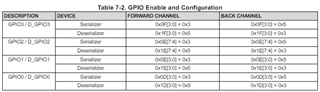
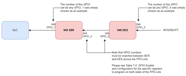
We use 948 and 949, 949 for the engine side, 948 for our products, there is  application that needs to use GPIO1 as the interrupt output pin, and pass through to the serializer. The pin is used as an interrupt signal, and the cockpit controller can initiate fault or event processing after receiving the signal. How do you configure GPIO1 for such applications? Thank you!

  • Hello,

    Please see the table below for how to set the GPIOs. The steps for this are also included in the 948A "7.3.9.1 GPIO[3:0] and D_GPIO[3:0]" and "7.3.9.2 Back Channel GPIO Configuration" sections.

    Best,

    Nikolas

  • Maybe there is something wrong with my statement. When the product has an alarm, gpio1 on the 948 side needs to be raised, and gpio1 on the 949 side will be sent to the soc as an interrupt signal. For such applications, how to configure gpio1 for 948 and 949?

  • Hello,

    The steps provided above apply to the statement you are outlining. The steps highlighted above indicate how to program the 948 DES for back channel communication with the 949 SER. From there, it can be sent from the 949 to the SoC via standard GPIO communication. Could you possibly clarify on any confusion that may still be present - happy to provide further assistance.

    Best,

    Nikolas

  • Thank you for your patient reply. My understanding is that all I need is to set GPIO1 as input, and there is no need for other operations.

  • Hello xudong,

    Nikolas will get back to you on Monday.

  • Hello,

    On the 948 DES side, one GPIO will have to function as the input of the interrupt from the product and another GPIO will have to function as the output of the interrupt to the SER. Both GPIOs will have to be individually programmed as inputs and outputs, respectively.

    On the 949 SER side, one GPIO will have to function as the input of the interrupt from the DES and another GPIO will have to function as the output of the interrupt to the SoC. Both GPIOs will have to be individually programmed as inputs and outputs, respectively.

    One additional note: for GPIO communication over the FPD-Link (i.e. between the 948 DES and 949 SER), the GPIO numbering must match. Please see below on what registers to write to (on both SER and DES side) for the GPIOs communicating over the FPD-Link.

    Please see the block diagram below for a example flow highlighted above. 

    Let me know if you have any further questions. If you know which GPIOs will be used where on both the SER and DES side, I would be happy to provide you with the specific register writes to program each individual GPIO.

    Best,

    Nikolas