Other Parts Discussed in Thread: TIDA-00204
Dear TI
I'm trying to EMC & LAN compliance test.
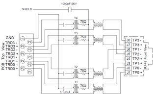
After checking the circuit diagram and B, please let me know which circuit to add
(Do MDI require additional circuit design?)

This thread has been locked.
If you have a related question, please click the "Ask a related question" button in the top right corner. The newly created question will be automatically linked to this question.
Dear TI
I'm trying to EMC & LAN compliance test.
After checking the circuit diagram and B, please let me know which circuit to add
(Do MDI require additional circuit design?)


Hello,
I would caution to ensure that the routing of RJ-45 is as required for IEEE802.3 (1-8 = A+,A-,B+,C+,C-,B-,D+,D-). I would also advise to have a quad channel magnetic instead of 4x single channel magnetic due to ensuring similar performance across channels.
Sincerely,
Gerome
Dear Gerome
It's hard to understand exactly.(IEEE802.3 ???)
Please recommend me the magnetic parts. (Do you mean to design the magnet individually?)
Please give me a design guide.
please check it
Hello,
Please refer to our EVM as an example for MDI routing.
Sincerely,
Gerome
Dear Gerome,
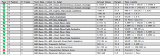
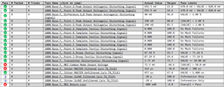
The following items failed during LAN test.
What are the ways to improve it?
please check it
[10Base-T]

[100Base-T]
[1000Base-T]
Hello,
Can you please compare your design against our schematic and layout checklist? Please consult DP83867 product page under "Design and Development" for these documents. Please send the completed documents here to help push this debug forward.
Sincerely,
Gerome
Dear Gerome
Share the schematic and LAN test results.
(1) ETHERNET_SCH.pdf
(2) Transformer : 48F-76NWZ2NL(REV1.1).pdf
(3) LAN test report : **.zip
please check it(attachment file)
Hello,
Can you please complete the below documents and send back for review?
https://www.ti.com/lit/zip/slvrbn1
https://www.ti.com/lit/zip/snlr048
Sincerely,
Gerome
Dear Gerome
I have answered within my knowledge.
Please check the attached file and answer.
Hello,
Some comments based on your response:
- MDI transformer looks to be a bit out of spec; turns ratio specification is higher (5%) than recommended (2%), while Insertion loss is also higher (-1.2dB at 100MHz). Would recommend looking at a different magnetic for your application.
- While layout pictures are helpful, they don't provide full picture of your design. Is the MDI less than 3" up to magnetic per checklist? Is it length matched accordingly? Is it 100 OHM differential impedance? Answering the questions in the checklist and provide said data would be better comparison of design against our recommendations.
Sincerely,
Gerome
Dear Gerome
I will change the magnet to the product in the guide as much as possible.
Is turns ratio(or insertion loss) the cause of problem "100base-Tx, Transmitter Return Loss" Test?
Impedance is differential 100ohm.
line length is matched.
I've adjusted the guide as much as possible.
If so, is the reason why the items below are problematic because of Transformer spec.?
[LAN Compliance Fail Item]
(1) 100base-Tx, Transmitter Return Loss
(2) 1000 Base-T, MDI Return Loss
(3) 1000 Base-T, MDI Common Mode Output Voltage
(4) 1000 Base-T, Jitter MASTER Filtered (w/o TX_TCLK)
please check it
There are also additional issues.
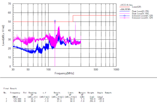
125 MHz band issue in EMC(VCCI class A).
How can I improve it?
Hello,
We do not have a strict correlative 1:1 of a component's parameter to test result. However, we have tested this device and have passed these tests. Thus is why we give out guidance, as we understand that each customer has unique design requirements and no two designs will be alike. If customer follows our guidance for their design, it can have advantageous effects.
Regarding EMC RE issues, what standard are you testing against? In addition, 125MHz is very synonymous with 1G RGMII. Can you please confirm the MAC interface?
Sincerely,
Gerome
Dear Gerome
I summarized the answers in two categories.
(1) LAN compliance test's failure
I know you want me to follow the guide as much as possible.
I understand the recommended specifications.
However, I have a question about the cause of 1G_return loss failure of LAN compliance test.
So, I asked you more about Transformer guide. (schematic review, Magnetic turn ratio, etc...)
(2) EMC test failure
It's a VCCI test in Japan. Connected the LAN and proceed with the VCCI test.
Like the image I attached, Spec. out at 125MHz(and 250MHz)
So, I think it's a problem caused by 1000base-T.
Based on the schematic attached on the May-22-2024,
I'm using the SGMII interface.
please check it
Hello,
Thank you for your query. Please expect a response by end of day tomorrow.
Sincerely,
Gerome
Hello,
Usually the cause for any compliance test would be the MDI circuitry/layout, or as a setup issue. Please confirm appropriate setup configuration with your scope vendor.
For VCCI test, we have not tested against this standard before; instead against CISPR11.
Sincerely,
Gerome
Dear Gerome
If 125MHz is a problem when testing, how can I improve it?
(1) DP83867 IC's shield can?
(2) Artwork pattern?
please check it
Hello,
By artwork pattern, do you mean silkscreen?
For the spur, perhaps different cable (shielded/different cable type) may affect this.
Sincerely,
Gerome
Dear Gerome
Artwork pattern means pcb impedance pattern(or clock line shielding).
Why connect capacitor to RJ45 pattern?
How to reduce 125 MHz noise?
The TI guide does not have a design using a shield can.
Are there any cases where I need to be careful when designing specific lines?
please check it
Hello,
Do you mean capacitor between RJ-45 GND and system GND? Usually that is a network for ESD protection.
Lets try to narrow down the potential sources.
Can you please gather the following information:
- Baseline Scan of Room
- Scan with board on, PHY powered off
- PHY held in reset
- PHY on, no link up
- PHY linked up, but no traffic sent
- PHY linked up, but in MAC isolate (Reg 0x0[10])
We also have only tested per CISPR 11 RE. We also have a reference design TIDA-00204.
Sincerely,
Gerome
Dear Gerome
We can do the EMC test in July.
I'll answer you then.
And, Is heat dissipation severe when using PHY?
The guide document does not about heat dissipation.
Do you have any reference documents?
I have a personal question.
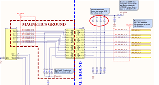
[Question#1]
What's the difference between products that design bias voltages
for transformers and those that don't?
Can I look at the design according to the PHY chip?
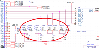
[Question#2]
Why did that design additional resistor(49.9R)?
Hello,
Power dissipation for this product is typically 0.5W but more information can be found in our power consumption app note, SNLA241.
I can't go into much behind the implementation of MDI circuitry of our device, but I can say that presence of PU resistors on MDI indicates current mode driver while absence indicates voltage mode driver.
Those networks on Q2 are Bob-Smith termination.
Sincerely,
Gerome
Dear Gerome
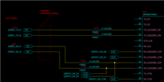
In my memory,
The AC-coupled capacitor of SGMII was placemented on the RX side, is it right?
In the image below,
Is it correct to place C103&C104 on the AP side and C105&C106 on the DP83867 side?
Hello,
In general, it is recommended to place these components close to the transmitter for best signal integrity practices.
Sincerely,
Gerome
Dear Gerome
What is the impact of placing on the RX-side?
Is there a reason for the placement?
Is there a maximum length of SGMII-line?
please check it.
Dear Gerome
I have an additional question.
(1) Is there a SGMII line length spec.?
(ex. Designed within 100mm)
(2) Do I have to match all the length of the MDI line?
Or, do I just need to match it in pairs?
(ex. MDI0+ & MDI0-=3.3mm, MDI1+ & MDI1-=3.5mm)
please check it
Hello,
It appears that there are some general board design questions that you are raising. I would like to make aware of a great document for this, SNLA387, and SNLR048A which can give good rules of thumbs collected over the years.
Placement of SGMII capacitor is for best practices from signal integrity standpoint.
For MDI, the bigger care about is intrapair length matching, but it would be helpful to have interpair length matching to be close to each other.
Sincerely,
Gerome