This thread has been locked.

If you have a related question, please click the "Ask a related question" button in the top right corner. The newly created question will be automatically linked to this question.

DS125DF1610: CDR Reset Procedure

Part Number: DS125DF1610

Hello E2E Experts,

Good day.

Reference E2E forum:

[FAQ] DS125DF1610: How to setup the device to generate different PRBS pattern - Interface forum - Interface - TI E2E support forums

I looked at the CDR reset procedures in the programming guide and in one of your link on the forum. There are some differences and I would like to clarify them.

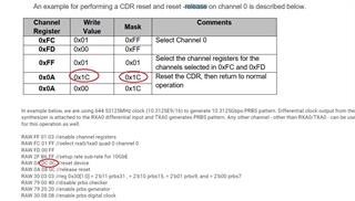
The procedure described in the programming manual (page 52) consists of:
RAW 0A 1C 1C // reset device
RAW 0A 00 1C // reset - release
That is, bits 2-4 of register 0x0A are first set to “1” and then reset to “0”.

The procedure described on the forum is different - the mask 0x0C is used, not 0x1C. That is, bit 4 of register 0x0A is not involved in the CDR-reset procedure.

Please tell me which option is correct.

P.S. I am attaching a screenshot with a description. Tell me please, do you see my screenshots? I don't see them in our correspondence.

Regards,

TI-CSC

  • Hi TI-CSC,

    It looks like there is a mistake in the programming guide. The correct procedure to perform a CDR reset is the following.

    (channel register, write value, mask)

    0x0A 0x0C 0x0C // place device in reset state

    0x0A 0x00 0x0C // release reset

    Note that bit 3 is an enable bit to override CDR reset with 0x0A[2]. Therefore, CDR reset can be released by writing (0x0A 0x08 0x0C) or (0x0A 0x00 0x0C).

    Best,

    Lucas

  • Thank you Lucas.

    Another question on the topic below:

    DS125DF1610: PRBS Generation with 10G/16 (644.35125MHz clock) input

    To check cdr lock the command was used:
    RAW 02 00 00 //read reg 0x02 0x02[4:3]=2'b11 this indicates cdr lock.
    But judging by the datasheet, register 0x02 requires additional configuration through register 0x0C[7:4], see the screenshot below.


    How should register 0x0C[7:4] be configured so that the cdr lock status can be read from register 0x02?

    Regards,

    TI-CSC

  • Hi TI-CSC,

    No change is necessary in register 0x0C. The default value, 0x0C[7:4]=0x0, can be used to check CDR lock in 0x02[4:3].

    Best,

    Lucas

  • Hello Lucas, 

    Good day.

    I need to generate a PRBS sequence from a DS125DF1610 retimer. As I understood from correspondence earlier, for a speed of 10.3125 Gbps, the correct reference frequency is 644.53125 MHz.
    What about speeds of 1.25Gbps, 2.5Gbps, 10Gbps? What reference frequencies should be in these cases?

    The diagram is shown below. LMX 2581 is used as a signal source.

    Regards,

    TI-CSC

  • Hi TI-CSC,

    To use the PRBS generator, the retimer needs to obtain CDR lock to an incoming signal. This is possible by transmitting a clock signal whose frequency is a sub-rate of the configured data rate. This sub-rate can be divide by 2, 4, 8, 16, etc. So at 10.3125 Gbps, the clock frequency can be 5.15625 GHz, 2.578125 GHz, 1.2890625 GHz, 644.53125 MHz, etc. At 1.25 Gbps/2.5 Gbps/10 Gbps, the clock frequency can be 625 MHz, 312.5 MHz, etc.

    Best,

    Lucas